Dosing device for mounting on a container

a technology for mounting devices and dosing devices, which is applied in the direction of liquid dispensing, containers, pliable tubular containers, etc., can solve the problems of large volume, inability to apply a solution to a dosing device that is not mounted, and complicated structure of this known dosing device, etc., to achieve the effect of simple and compact structur

Inactive Publication Date: 2005-12-01
JENSEN BJORN SLOT +2
View PDF14 Cites 21 Cited by
  • Summary
  • Abstract
  • Description
  • Claims
  • Application Information

AI Technical Summary

Benefits of technology

[0007] The object of the present invention is to provide a dosing device that is simpler and more compact than prior-art devices.

Problems solved by technology

However, the structure of this known dosing device is very complicated and thus expensive.
Furthermore, because of the permanently open connection between the dosing chamber and the expansion chamber, the solution cannot be applied to a dosing device that is not mounted in a fixed position, because liquid then would be able to leak through the expansion chamber to the surroundings.
Moreover, the expansion chamber results in a bulky device and is not satisfactory in terms of hygiene requirements, as a surplus quantity of liquid will be continuously in contact with the surrounding air, and as the device is difficult to clean.
However, the structure of this apparatus is very bulky and therefore costly.
In addition, the upward movement of the armature has a tendency to lift the dosing apparatus and bottle out of its position in the electric coil at dispensing.
Furthermore, as the dosing chamber is located in the housing that is inserted in the electric coil, a very large coil is necessary, thereby adding considerably to the costs of the apparatus.
Consequently, the price of each coil is very important for the overall costs of the dispensing system.
However, the solenoid necessary to actuate the valve has a size approximately equivalent to the size of the flask, whereby the entire liquid dispenser is very bulky and has to be mounted in a fixed position.

Method used


Image

  • Dosing device for mounting on a container
  • Dosing device for mounting on a container
  • Dosing device for mounting on a container

Examples


Embodiment Construction

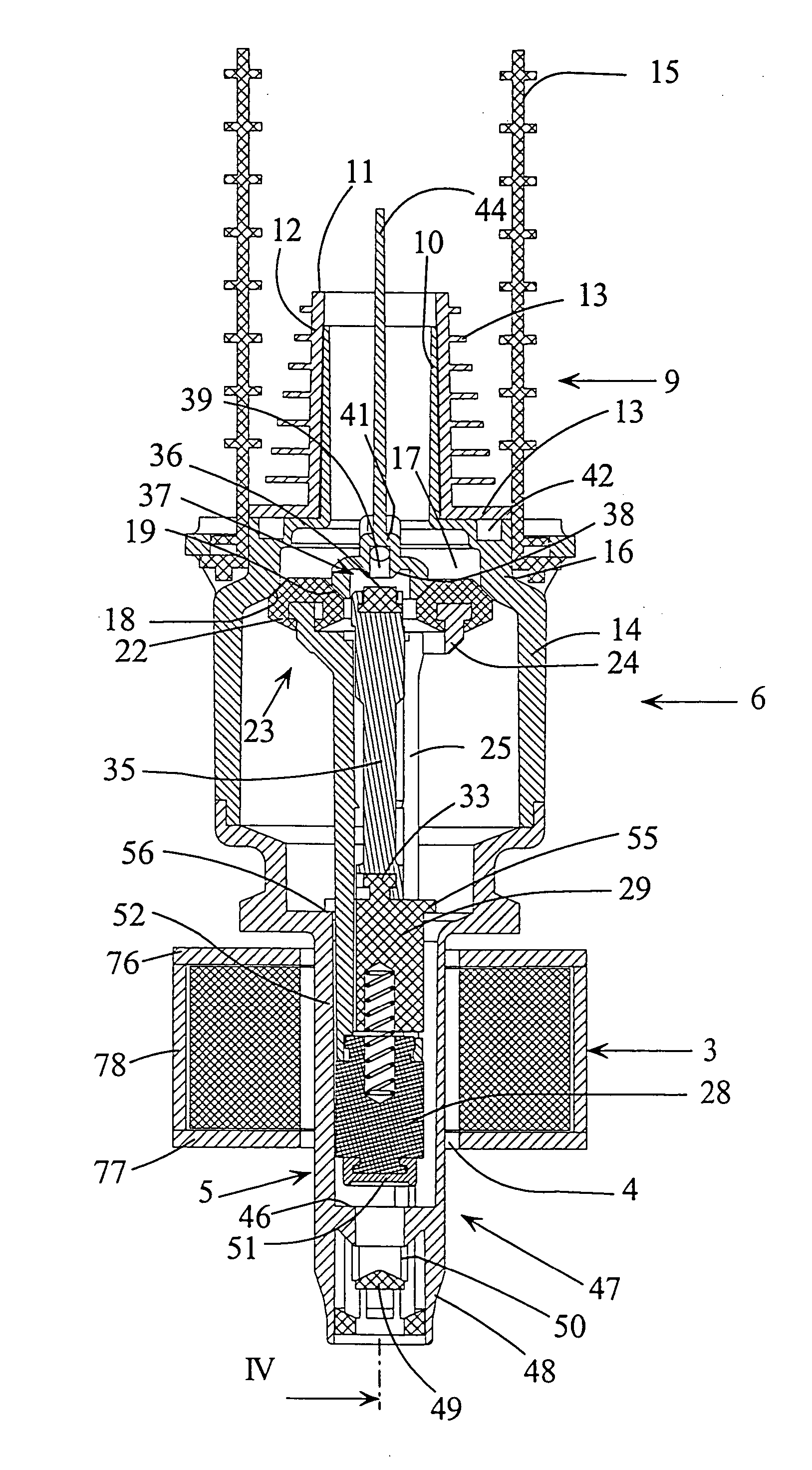
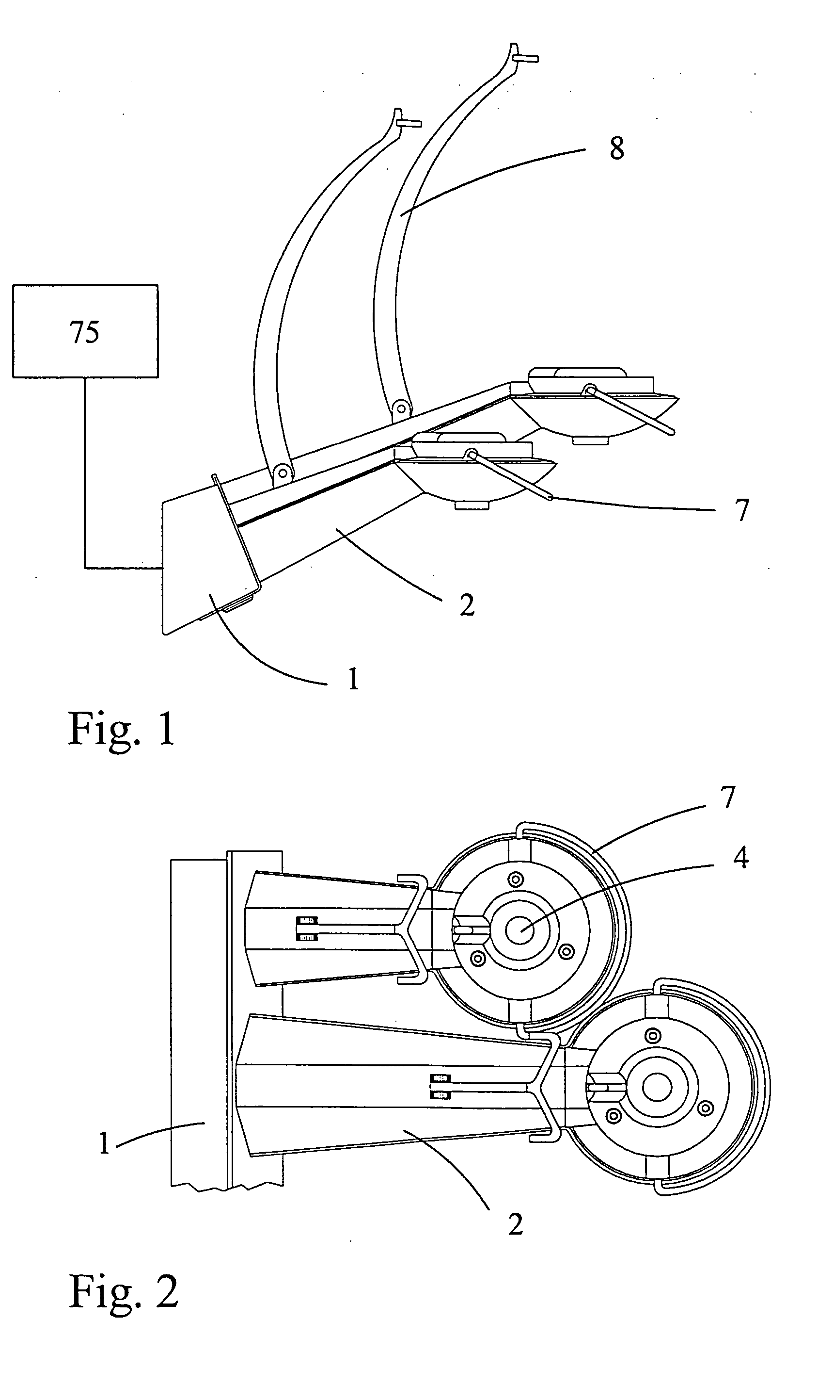
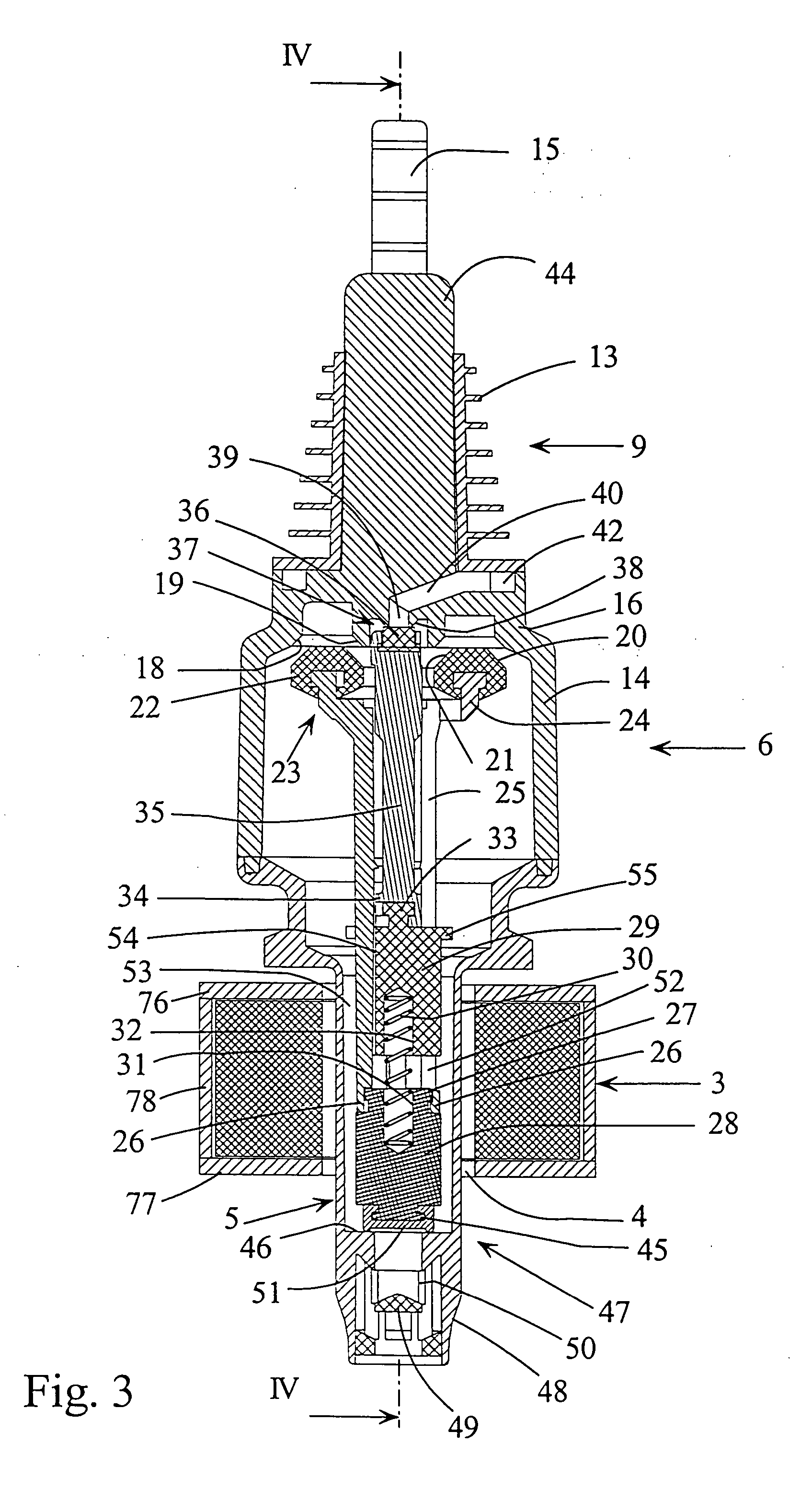
[0044]FIG. 1 is a side view of a panel I comprising several bottle holders 2, of which only two are shown, provided with an electromagnetic coil 3, shown in FIGS. 3 and 4, located around a central opening 4 in the bottle holder 2. An outlet spout 5 of a dosing device 6 according to the invention, mounted on the neck of a bottle, may be inserted into the opening 4 from above, so that the bottle may be supported upside down on the bottle holder 2. In this position, the spout 5 will project from the bottom side of the bottle holder 2, so that liquor may be dispensed from the spout 5 upon activation of the electromagnetic coil 3. The activation of the coil 3 may be initiated by pressing a switch in the form of a lever arm 7 on the bottle holder 2. The bottle holders 2 are provided with supplementary support arms 8 for the bottles.

[0045] The dosing device according to the invention is not only suitable for dispensing of liquor, but can advantageously be applied for many different purpos...


PUM


Abstract

A dosing device comprises a dosing chamber associated with a liquid inlet valve and a liquid outlet valve. Each said valve has a valve body being displaceable by menas of an armature located in an outlet spout and being displaceable by means of a magnetic field. The dosing device is operable between a charging state, in which the liquid inlet valve is open, and the liquid outlet valve is closed, and a dispensing state, in which the liquid inlet valve is closed, and the liquid outlet valve is open. The spout comprises two armatures adapted to influence each other by means of a magnetic force, and the dosing chamber is provided with an air intake valve having a valve body operable between a closed position in the charging state of the dosing device and an open position in the dispensing state of the dosing device.

Description

BACKGROUND OF THE INVENTION [0001] The present invention relates to a dosing device for mounting on a container, the dosing device comprising a dosing chamber associated with a liquid inlet valve for communication with the container and a liquid outlet valve for communication with a mouth of an outlet spout, the outlet spout being arranged adjacent to and having a substantially smaller outer diameter than the dosing chamber, each said valve having a valve body being displaceable between a closed position and an open position by displacement of an armature located in the outlet spout, the armature being displaceable by means of a magnetic field generated by an electromagnetic coil in which the spout may be inserted, the dosing device being operable between a charging state, in which the liquid inlet valve is open, and the liquid outlet valve is closed, and a dispensing state, in which the liquid inlet valve is closed, and the liquid outlet valve is open, and the dosing chamber being ...

Claims


Application Information

Patent Timeline
Patent Type & Authority Applications(United States)
IPC IPC(8): B65D35/56B67D3/00G01F11/32
CPCB67D3/0045G01F11/32B67D2210/00144
Inventor JENSEN, BJORN SLOTLINDBERG, FRANKLINDBERG, PETER
Owner JENSEN BJORN SLOT
Why Eureka
Try Eureka