Exhaust gas aftertreatment system

a technology of exhaust gas and aftertreatment system, which is applied in the direction of exhaust treatment, inorganic chemistry, and using liquid separation agents, can solve the problems of not insignificant installation space and complex system design, and achieve the effect of easy adaptation to internal combustion engines, small space, and easy realization

Inactive Publication Date: 2011-07-28
HILTI AG
View PDF6 Cites 2 Cited by
  • Summary
  • Abstract
  • Description
  • Claims
  • Application Information

AI Technical Summary

Benefits of technology

[0003]It is an object of the present invention to provide an exhaust gas aftertreatment system that is simpler and more compact than those known in the art, and also to provide a method for operating such an exhaust gas aftertreatment system.
[0006]In another aspect of the present invention, an introducing means for introducing hydrocarbons, in particular in the form of fuel, is disposed upstream of the catalyst. In a further aspect of the present invention, the introducing means and the introduction device for introducing a reducing agent, such as “AdBlue®”, generically AUS32, are combined into one unit. This enables a compact design requiring little space. Preferably, the introducing means and / or the introduction device are placed directly at the internal combustion engine in the exhaust line that includes also the exhaust manifold, which collects the exhaust gas streams from the individual cylinders. This makes it possible to integrate the required control lines into existing wiring harnesses, and to integrate the control into an existing internal combustion engine controller. However, especially due to the integration into one unit, it is important that the introducing means and the introduction device be operated alternately. It must be ensured that only one system is active at any one time, which can be easily accomplished using suitable blocking means. This is assisted by the direct connection to the internal combustion engine.
[0007]In yet another aspect of the present invention, the catalyst and the particulate filter are combined into one unit, the particulate filter being located downstream of the catalyst. This further unit provides an overall extremely compact system, which is easily adaptable to an internal combustion engine and / or to a vehicle or a tool, even in very confined mounting environments. This ease of adaptation is assisted by the fact that the catalyst and the particulate filter need not be controlled externally, so that there is no need to route cables to these components.

Problems solved by technology

This system is complex in design and requires a not insignificant amount of installation space because the individual components are arranged in series one behind the other.

Method used


Image

  • Exhaust gas aftertreatment system
  • Exhaust gas aftertreatment system

Examples


Embodiment Construction

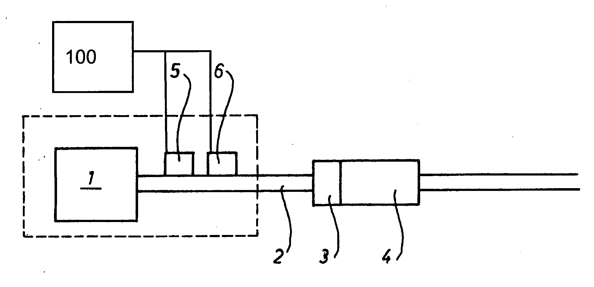
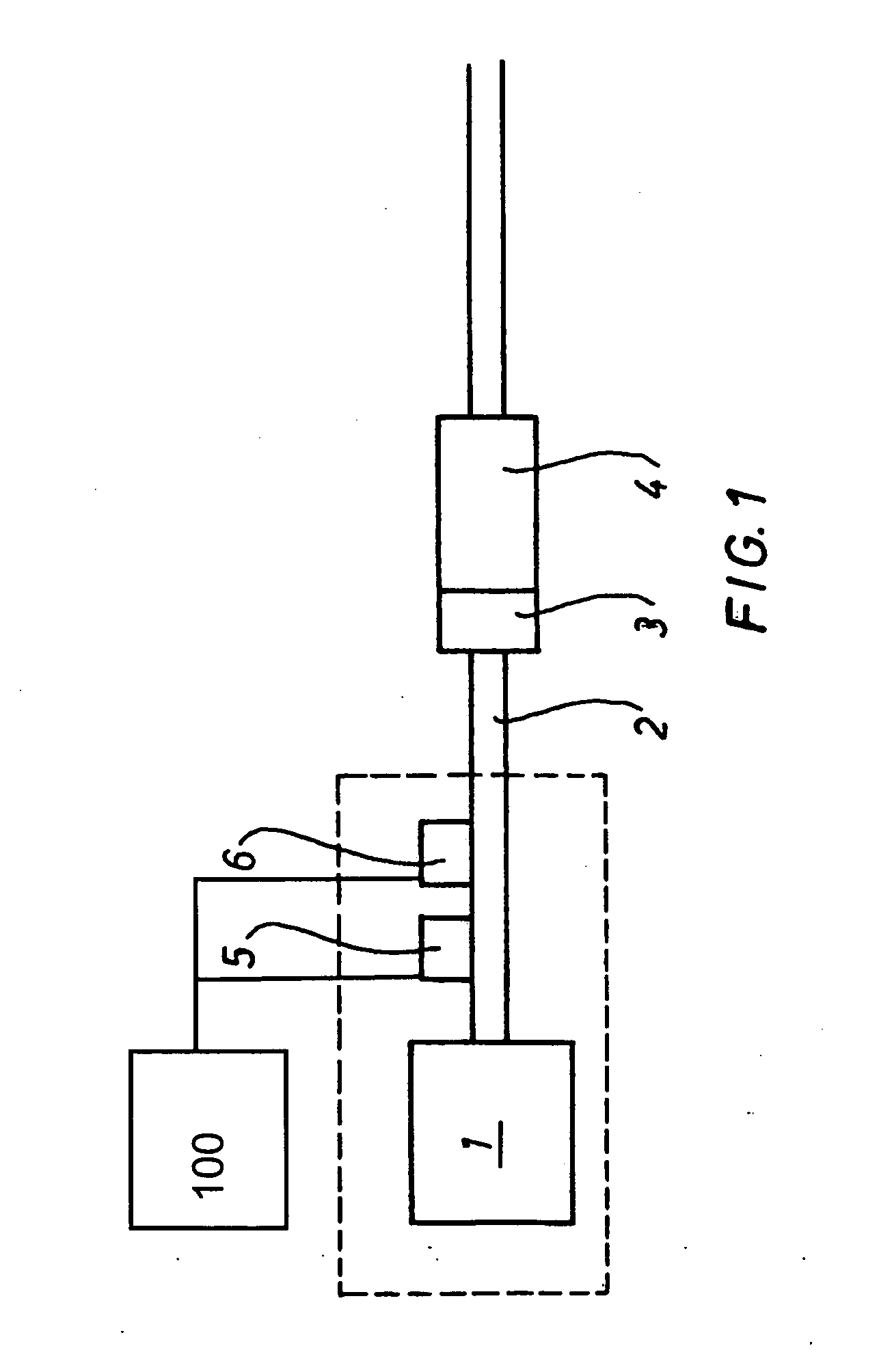
[0009]The only figure is a schematic view showing an internal combustion engine 1, which may be any type of Diesel engine. An exhaust line 2 (including an exhaust manifold) is connected to the exhaust ports of the engine. The exhaust gas emitted by the internal combustion engine during operation is passed through said exhaust line, subjected to exhaust aftertreatment (and possibly also to noise reduction), and is ultimately released into the environment. In order to treat the exhaust gas, the exhaust gas is initially passed through a catalyst 3 capable of being operated in both the reductive and oxidative mode, and subsequently through a particulate filter 4 (soot filter). In order to thermally regenerate particulate filter 4, the required temperature of about 400 ° C. is generated in catalyst 3 by exothermic oxidation of hydrocarbons (especially in the form of Diesel fuel). To this end, the hydrocarbons are introduced into the exhaust line via an introducing means or hydrocarbon in...


PUM

PropertyMeasurementUnit
temperatureaaaaaaaaaa
timeaaaaaaaaaa
temperatureaaaaaaaaaa

Abstract

An exhaust gas post treatment system for, in particular, a self-igniting internal combustion engine including a catalytic converter that is arranged in an exhaust gas line, a fine particle filter and an introduction device for a reduction agent arranged upstream of the catalytic converter in the direction of the flow of the exhaust gas, and to a method for operating said type of exhaust gas post treatment system. An exhaust gas post treatment system and a method for operating said type of system that is simple to use and compact. This is achieved by virtue of the fact that the catalytic converter is a reductively or oxidatively operated catalytic converter, or that the introduction device, the catalytic converter, that can be operated reductively or oxidatively, and the fine particle filter are arranged in said sequence and in the exhaust line in the direction of flow.

Description

[0001]The present invention relates to an exhaust gas aftertreatment system, in particular for an auto-ignition internal combustion engine, including a catalyst located in an exhaust line, a particulate filter, and an introduction device for introducing a reducing agent upstream of the catalyst in the direction of the exhaust gas flow. The present invention further relates to a method for operating such an exhaust gas aftertreatment system.BACKGROUND[0002]An exhaust gas aftertreatment system of this type is described, for example, in European Patent EP 1 054 722 B1. This system provides a method and a device, wherein the pollutant-containing exhaust gas of a Diesel engine is initially introduced into an oxidation catalyst to convert NO contained in the gas stream to NO2, and to increase the NO2-content in the gas stream. Subsequently, the gas stream is introduced into a particulate filter to remove, in particular, soot from the exhaust gas. Then, the gas stream is fed into an SCR ca...

Claims


Application Information

Patent Timeline
Patent Type & Authority Applications(United States)
IPC IPC(8): B01D53/94B01D50/00
CPCB01D53/9409Y02T10/24B01D2251/2067B01D2251/208B01D2255/20723B01D2255/50B01D2258/012F01N3/0253F01N3/035F01N3/2066F01N2250/02F01N2610/02F01N2610/03F01N2610/14B01D53/944Y02T10/12
Inventor BROLL, PETER
Owner HILTI AG
Why Eureka
Try Eureka