
Running Gear with a Single Pair of Independent Left and Right Wheels and Lateral Stop Means, and Associated Low Floor Rail Vehicle

a running gear and lateral stop technology, applied in the direction of wheel axle self-adjustment, axle-box mounting, underframes, etc., can solve the problem of limited transverse movement of the fram

Active Publication Date: 2020-05-28
BOMBARDIER TRANSPORTATION GMBH
View PDF0 Cites 2 Cited by
  • Summary
  • Abstract
  • Description
  • Claims
  • Application Information

AI Technical Summary

Benefits of technology

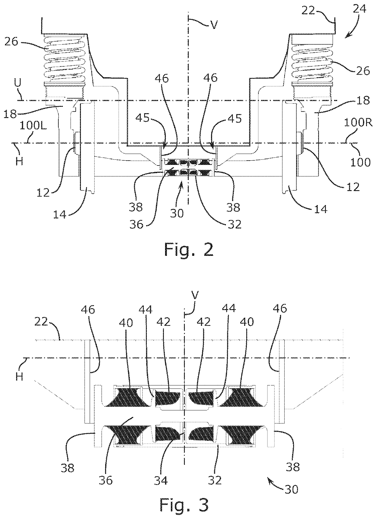
This patent is related to a buffer system for a rail vehicle that reduces movement between the vehicle body and the running gear in a transverse direction of the rail vehicle. The buffer system includes two subassemblies consisting of a vehicle body and a running gear, each with a lateral stop device. The first lateral stop device has a fixed support, a movable carrier with opposite contact faces, and elastomeric bodies for limited movement of the carrier. The second lateral stop device has corresponding contact faces at a distance. The buffer system also includes elastic buffer bodies between the movable carrier and the fixed support to counteract movement beyond a certain threshold. The technical effect is a more effective and efficient buffer system that absorbs peak forces and reduces vibration during rail vehicle movement.

Problems solved by technology

Movements of the frame in the transverse direction are limited by abutment stops, which are arranged on guide brackets fixed to the car body laterally on each side of the running gear frame, which is only possible because the width of the vehicle body is substantially greater than the width of the running gear.
Hence, the underbody of the vehicle body is located substantially above the wheels and the running gear appears to be inappropriate for a low floor vehicle.

Method used


Image

  • Running Gear with a Single Pair of Independent Left and Right Wheels and Lateral Stop Means, and Associated Low Floor Rail Vehicle
  • Running Gear with a Single Pair of Independent Left and Right Wheels and Lateral Stop Means, and Associated Low Floor Rail Vehicle
  • Running Gear with a Single Pair of Independent Left and Right Wheels and Lateral Stop Means, and Associated Low Floor Rail Vehicle

Examples


Embodiment Construction

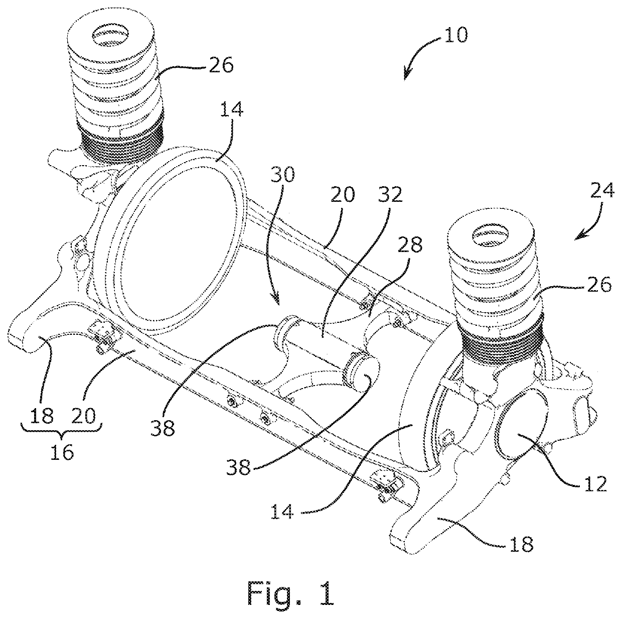
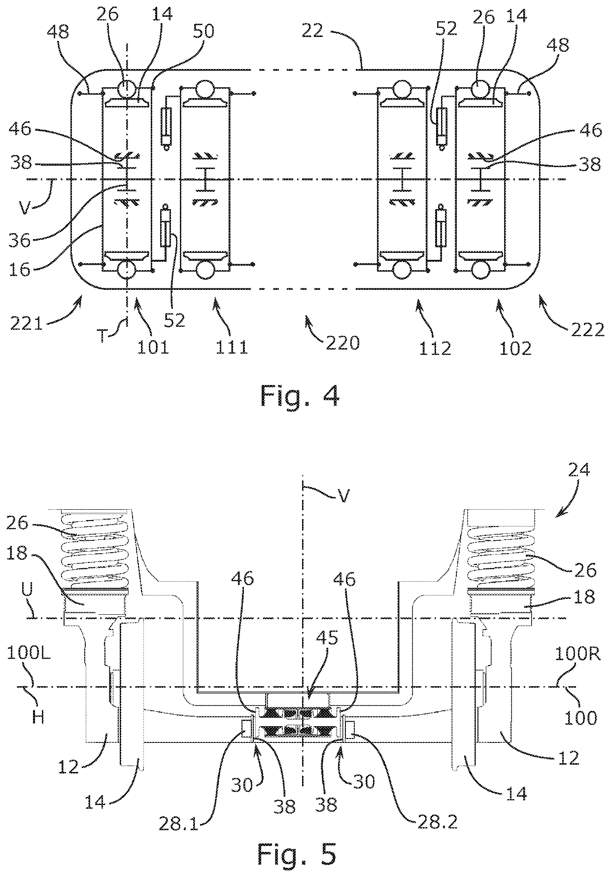
[0040]With reference to FIG. 1, a running gear 10 for a rail vehicle has a pair or left and right rotation bearings 12 for guiding a pair of independent left and right idle wheels 14, which are located between the left and right rotation bearings 12. The wheels 14 are independent wheels in the sense that they do not share a common wheel axle and can spin about their respective spin axes 100L, 100R independently from one another. The running gear 10 is provided with a rectangular frame 16, comprised of two longitudinal beams 18, each integrally formed with a respective one of the left and right rotation bearings 12, and two front and rear transverse beams 20 that extend, between the two front ends, respectively the two rear ends, of the longitudinal beams 18, so that the wheels 14 viewed from above are contained within the rectangular frame 16.

[0041]To support the load of a vehicle body 22 of the rail vehicle, a vertical secondary suspension 24 is installed directly between the bogie...


PUM


Abstract

A running gear for a low floor rail vehicle includes a frame, a single pair of independent left and right wheels, and a single pair of left and right rotation bearings attached to the frame that allow the left and right wheels to independently spin about a left and right spin axis, respectively. The running gear further includes a secondary suspension resting on the frame for supporting a vehicle body of the rail vehicle and lateral stop means fixed to the frame for laterally guiding the vehicle body of the rail vehicle. The lateral stop means includes a left and a right contact face facing a left and a right, respectively, transverse direction parallel to the transverse reference axis. The left and right contact faces are located between the left and right wheels.

Description

CROSS-REFERENCE TO RELATED APPLICATION[0001]This application claims priority to United Kingdom Patent Application No. 1819025.6 filed Nov. 22, 2018, the disclosure of which is hereby incorporated by reference in its entirety.BACKGROUND OF THE INVENTIONField of the Invention[0002]The present invention relates to a running gear with a single pair of independent left and right wheels and to a rail vehicle provided with such a running gear.Description of Related Art[0003]A rail vehicle provided with running gears having a single pair of independent left and right wheels, i.e. wheels that can rotate independently from one another, is known from KR101498450B1. Each running gear has a pair or left and right rotation bearings for guiding a pair of left and right idle wheels, which are located between the left and right rotation bearings. The running gear is provided with a rectangular frame with two longitudinal beams extending each above one of the rotation bearings and two transverse beam...

Claims


Application Information

Patent Timeline
IPC IPC(8): B61F5/24B61F1/14B61F3/00
CPCB61F5/24B61F3/00B61F1/14B61F5/30B61F5/38B61F5/308B61F5/304B61F3/16B61F5/06B61F5/32
Inventor BIEKER, GUIDOPIEPER, REINHARD
Owner BOMBARDIER TRANSPORTATION GMBH
Learn More