Magnetic bearing using displacement winding techniques

a technology of magnetic bearings and winding techniques, applied in the direction of magnetic bearings, propulsion systems, mechanical energy handling, etc., can solve the problems of reducing motor controllability, bearings tend to be non-linear, and fail to produce additional force or torqu

Inactive Publication Date: 2005-12-01
AIREX CORP
View PDF16 Cites 22 Cited by
  • Summary
  • Abstract
  • Description
  • Claims
  • Application Information

AI Technical Summary

Benefits of technology

[0012] In one aspect, the present invention provides a toothless permanent magnet motor, composed of a permanent magnet rotor and a Zigzag stator winding containing at least two-phase windings, where each phase is constructed of at least two circuits. Other exemplary embodiments include a trapezoidal winding configuration. The individual circuits of a phase are displaced away from each other along a line that is at right angles to the direction of the alternating polarity magnet array. The two circuits share the same “slot”, and each circuit resembles a complete phase winding, however, each contains half the total number of turns of the phase. Controllable axial bearing force is developed through the differential balance of the currents in the circuits, while required motor torque is generated by the sum of the individual currents in a given phase. The relative motion in the rotor can produce Back EMF which can provide positional information; A) in the direction parallel to the magnet array via the sum of the voltages in a phase; B) in the direction normal to the magnet array via the difference in circuit voltages.
[0015] This invention, when coupled with the appropriate sensing electronics, can allow the real-time measurement of angular, radial, and axial position of the moving member, thus eliminating numerous discrete sensors (and associated electronics) that are required in closed loop control applications.

Problems solved by technology

Higher values of inductance decrease motor controllability due to restricted actuator response bandwidth.
Tooth type motors and Electromagnetic (EM) bearings tend to be non-linear in torque and force production for high values of torque, and can completely fail to produce additional force or torque on peak demands due to flux saturation in the tooth type iron structures.
Internal forces loading the motor shaft can be caused through differential magnetic pull created by deviations in rotor magnet-to-magnet strength as well as rotor centrality errors.
In toothless motors, axial forces are present between individual rotor magnets and adjacent current carrying coil end-turns, but the geometric balance over the entire motor results in the gross cancellation of most of these forces.
The typical resulting combination of EM Bearing and BLDC motor is physically large due to the lack of a common housing and magnetic circuit integration.
In addition, the resulting system is significantly susceptible to loading by the forces described above, and suffers performance debits due to the high inductance.
Due to the large magnetic gap and sufficiently thick radial band of back iron, toothless motors are quite immune to magnetic saturation, however; the removal of heat generated within the winding throughout such peak demands requires significant design consideration.

Method used


Image

  • Magnetic bearing using displacement winding techniques
  • Magnetic bearing using displacement winding techniques
  • Magnetic bearing using displacement winding techniques

Examples


Embodiment Construction

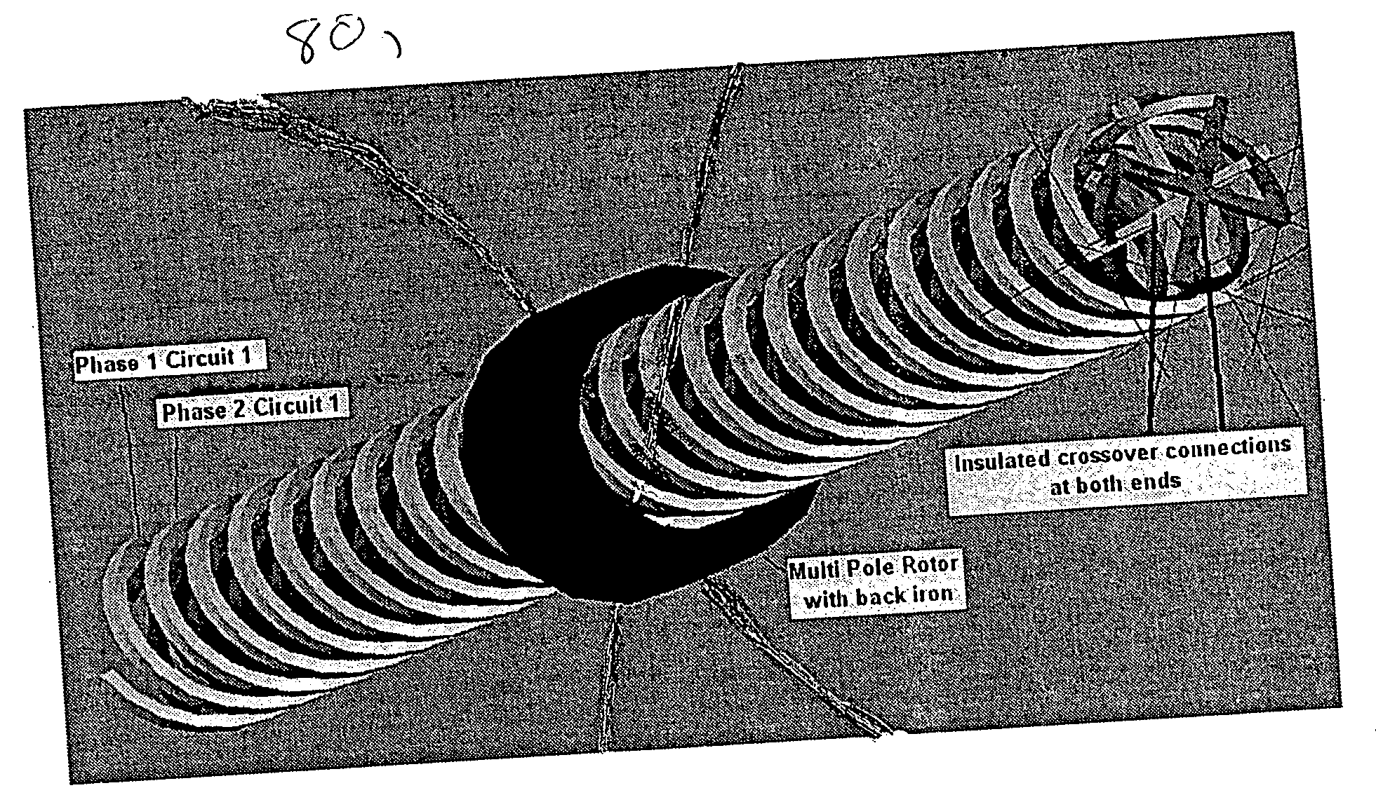
[0032] The following invention utilizes the toothless motor coils to simultaneously generate dynamically controllable forces on the rotating member (the rotor shaft system). The resulting motor-bearing system is capable, with the support of advanced control capabilities, of high performance attributes such as fine shaft centering, auto balancing, and vibration isolation.

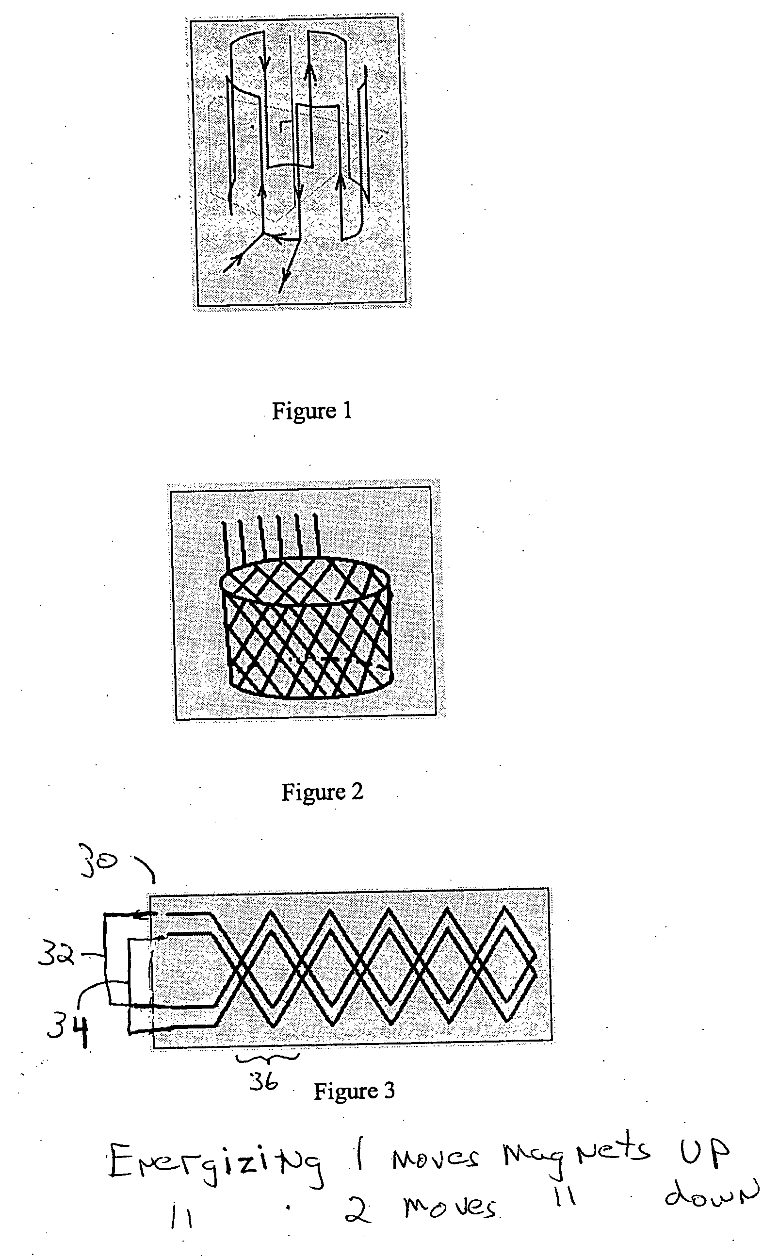
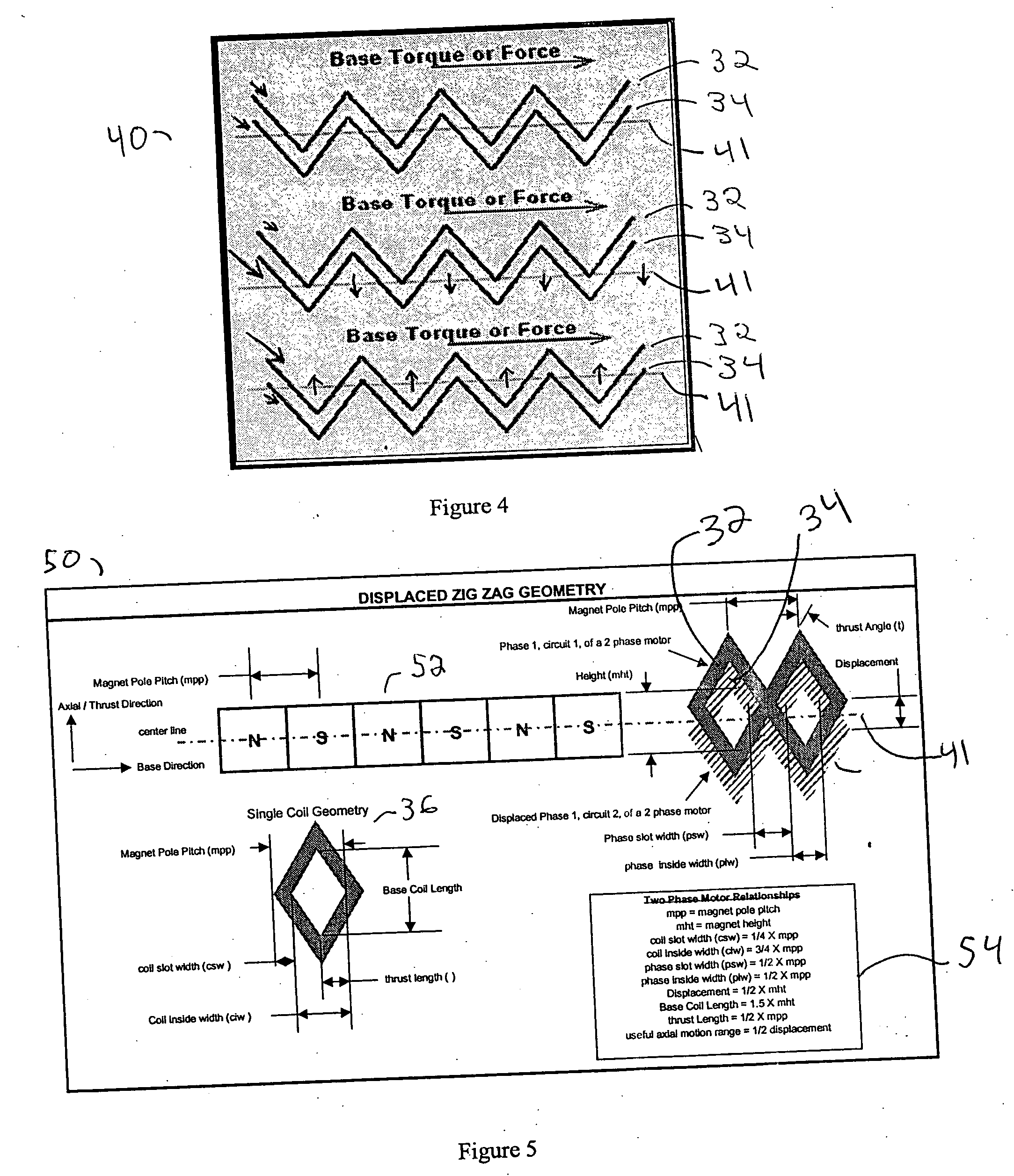
[0033] This invention describes a set of exemplary winding arrangements, which when applied to a toothless motor or any motor where the current carrying conductors are in the flux gap, allows the simultaneous production of motoring torque (or force for a linear configuration), and controllable forces directed along selected vectors (such as in the thrust or radial direction). The fundamental element of this invention is the concept of two or more independent circuits (windings) each representing a motor phase, where the actions of the differential currents in these circuits determine the magnitude and direction of r...


PUM


Abstract

The present invention provides a linear, rotary spherical motor with an integrated magnetic bearing. The motor can be a toothless permanent magnet, BLDC design composed of a permanent magnet rotor and a Zigzag stator winding containing at least two-phase windings, where each phase is constructed of at least two circuits. Other exemplary embodiments include a trapezoidal winding configuration. The individual circuits of a phase are displaced away from each other along a line that is at right angles to the direction of the alternating polarity magnet array. The circuits forming a phase share the same “slot”, and each circuit resembles a complete phase winding, however each circuit contains a proportion of the total number of turns of the phase. Controllable axial bearing force is developed through the differential balance of the currents in the circuits, while required motor torque is generated by the sum of the individual currents in a given phase. The relative motion in the rotor can produce back EMF which can provide positional information; A) in the direction parallel to the magnet array via the sum of the voltages in a phase; B) in the direction normal to the magnet array via the difference in circuit voltages.

Description

[0001] This application claims the benefit of U.S Provisional Application Ser. No. 60 / 569,960 filed May 10, 2005, the teachings of which are hereby incorporated by reference in its entirety.[0002] The U.S. Government has a paid-up license in this invention and the right in limited circumstances to require the patent owner to license others on reasonable terms as provided for by the terms of Contract Number 29601-01-C-0174 awarded by the Department of Defense.FIELD OF THE INVENTION [0003] The present invention relates to a magnetic bearing system and method using displaced winding techniques. More particularly, the present invention describes a linear, rotary or spherical permanent magnet Brushless Direct Current (BLDC) motor capable of producing controllable, simultaneous, rotational torque and directional force via a displaced winding arrangement. BACKGROUND OF THE INVENTION [0004] Tooth type and toothless Permanent Magnet (PM) motors produce torque between the stator and the PM ro...

Claims


Application Information

Patent Timeline
Patent Type & Authority Applications(United States)
IPC IPC(8): H02K7/09H02K29/00H02K41/03
CPCF16C32/044H02K7/09H02K2201/18H02K41/03H02K29/03H02K21/12
Inventor CARROLL, DAVIDSALWEN, JOHN
Owner AIREX CORP
Why Eureka
Try Eureka