Plasma display panel having improved exhaust efficiency

a technology of plasma display panel and exhaust efficiency, which is applied in the direction of gas-filled discharge tube, gas exhaustion means, electrodes, etc., can solve the problems of deteriorating display quality and gas moving well during gas exhaustion

Inactive Publication Date: 2005-12-01
SAMSUNG SDI CO LTD
View PDF5 Cites 5 Cited by
  • Summary
  • Abstract
  • Description
  • Claims
  • Application Information

AI Technical Summary

Problems solved by technology

However, in the PDP where barrier ribs surround the discharge cells on all sides, gas may not move well during gas exhaustion.
If impurity gas remains inside the PDP, a poor discharge may occur while driving the PDP, thereby causing discharge lines or spots at various points of a PDP screen, which deteriorates display quality.

Method used


Image

  • Plasma display panel having improved exhaust efficiency
  • Plasma display panel having improved exhaust efficiency
  • Plasma display panel having improved exhaust efficiency

Examples


Embodiment Construction

[0027] Hereinafter, with reference to the accompanying drawings, embodiments of the present invention will be described in detail in order that those skilled in the art will be able to implement it. As those skilled in the art would realize, the described embodiments may be modified in various different ways, all without departing from the spirit or scope of the present invention. The same reference numbers refer to the same or like parts.

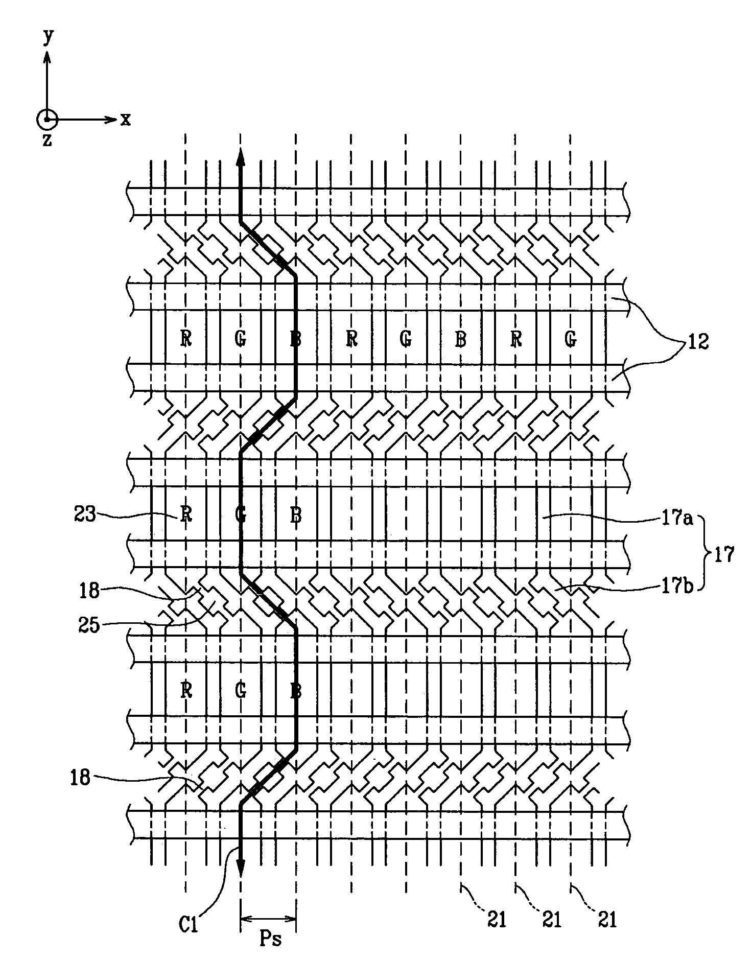
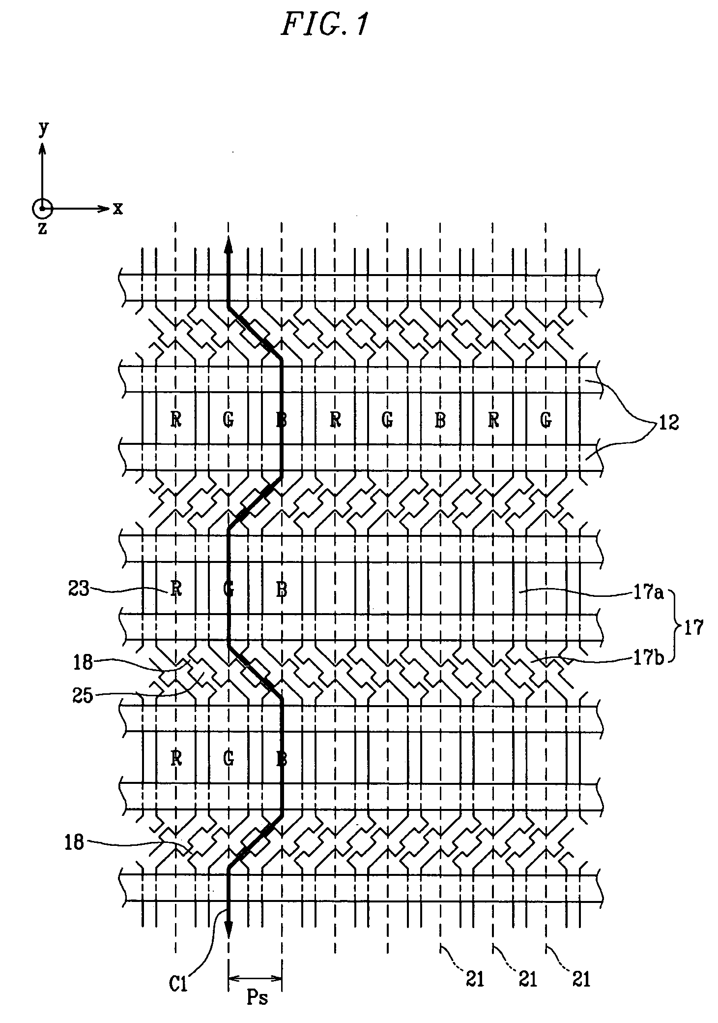
[0028]FIG. 1 is a top plan view partially showing a plasma display panel (PDP) according to a first exemplary embodiment of the present invention.

[0029] Referring to FIG. 1, the PDP according to the present embodiment may include a first substrate (not shown) and a second substrate (not shown) facing each other with a predetermined gap therebetween, and a barrier rib 17 partitions the space between the two substrates to define a plurality of discharge cells 23. A plurality of display electrode groups are formed along one direction (i.e., the x-ax...


PUM


Abstract

A plasma display panel including a first substrate and a second substrate, a plurality of address electrodes, a plurality of display electrodes, and a barrier rib. The address electrodes and the display electrodes are formed between the first and second substrates. The barrier rib is disposed in a space between the first and second substrates and defines a plurality of discharge cells. A gas exhaust passageway is formed between discharge cells neighboring each other along a diagonal direction. The passageways and the discharge cells cooperatively form a gas exhaust route that repeats breaking away by a predetermined pitch, and returning, thereby zigzagging along an elongation direction of the address electrode.

Description

CROSS REFERENCE TO RELATED APPLICATION [0001] This application claims priority to and the benefit of Korean Patent Application No. 10-2004-0038927, filed on May 31, 2004, which is hereby incorporated by reference for all purposes as if fully set forth herein. BACKGROUND OF THE INVENTION [0002] 1. Field of the Invention [0003] The present invention relates to a plasma display panel. More particularly, the present invention relates to a plasma display panel having a barrier rib structure that may improve exhaust efficiency during combining and gas exhausting steps of a panel manufacturing process. [0004] 2. Discussion of the Background [0005] Generally, a plasma display panel (PDP) is a display device that excites phosphors with vacuum ultraviolet rays radiated from plasma obtained through gas discharging, and displays desired images using red R, green G, and blue B colors generated by the excited phosphors. The PDP has several advantages. It may be made with a large screen of 60″ or ...

Claims


Application Information

Patent Timeline
Patent Type & Authority Applications(United States)
IPC IPC(8): H01J11/12H01J11/22H01J11/24H01J11/26H01J11/34H01J11/36
CPCH01J11/12H01J2211/361H01J11/54H01J11/36
Inventor CHUN, BYOUNG-MINKIM, JEONG-NAMKIM, TAE-WOOYI, JEONG-DOO
Owner SAMSUNG SDI CO LTD
Why Eureka
Try Eureka