Endoscope

a color imaging and endoscope technology, applied in the field of endoscopes, can solve the problems of difficult to obtain high resolution and good color reproduction, and achieve the effects of high quality image, excellent red color component resolution, and good quality

Inactive Publication Date: 2005-12-01
FUJIFILM CORP
View PDF5 Cites 32 Cited by
  • Summary
  • Abstract
  • Description
  • Claims
  • Application Information

AI Technical Summary

Benefits of technology

[0030] This endoscope has an excellent resolution of red color components and is suitable for photographing a good quality image of the interior of a living body having large red color components.
[0031] According to the present invention, it is possible to provide an endoscope capable of obtaining a high quality image.

Problems solved by technology

If a medical endoscope using a solid state imaging unit with a pixel number ratio of red (R), green (G) and blue (B) of 1:2:1 is used for photographing organs or tissues in a human body, it is difficult to obtain an image of high resolution and good color reproduction.

Method used


Image

  • Endoscope
  • Endoscope
  • Endoscope

Examples


Embodiment Construction

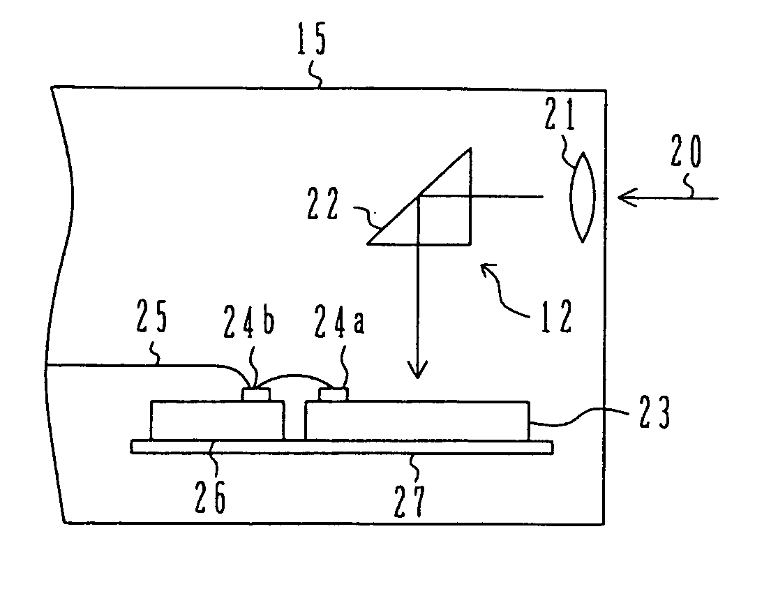
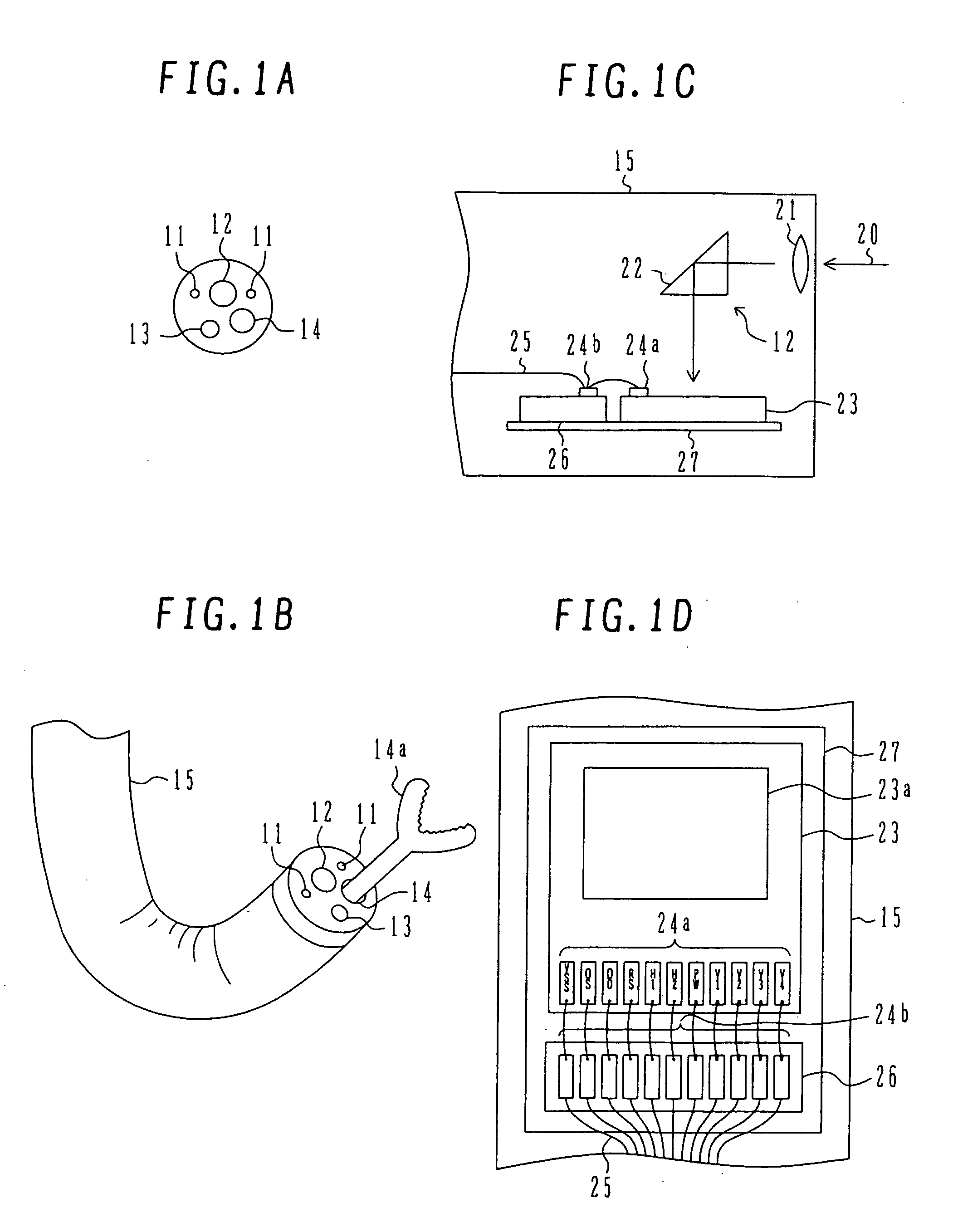
[0035]FIG. 1A is a schematic plan view showing the outline of a tip portion of an optical magnification electronic scope for observing precisely an upper digestive tract, FIG. 1B is a perspective view showing the tip portion of the scope and a tube connected to the tip portion, and FIGS. 1C and 1D are schematic diagrams showing an observation optical system of the scope.

[0036] Referring to FIG. 1A, the tip portion of an optical magnification electronic scope for observing precisely an upper digestive tract, is of generally the circular shape having a diameter of, e.g., 10.8 mm. This tip portion is constituted of a light source 11 with two light output openings, an observation optical system 12, a nozzle 13 and a forceps opening 14. The light source 11 includes a light emission source, a light guide (fiber) and light output openings. The electronic scope is used, for example, as a photogastroscope.

[0037] The light source 11 emits white light with light in the infrared range being c...


PUM


Abstract

An endoscope including: a light source for emitting light; a solid state imaging unit comprising a plurality of photoelectric conversion elements for accumulating signal charges corresponding to an incidence light amount, transfer units for transferring signal charges accumulated in the photoelectric conversion elements, and a plurality of color filters formed above the photoelectric conversion elements; and a transmission tube accommodating the light source and the solid state imaging unit, wherein the color filters include red, green and blue color filters, and the number of red photoelectric conversion elements upon which light transmitted through the red color filters are incident is larger than the number of green photoelectric conversion elements upon which light transmitted through the green color filters are incident and the number of blue photoelectric conversion elements upon which light transmitted through the blue color filters are incident. The endoscope can obtain a high quality image.

Description

CROSS REFERENCE TO RELATED APPLICATION [0001] This application is based on and claims priority of Japanese Patent Application No. 2004-156509 filed on May 26, 2004, the entire contents of which are incorporated herein by reference. BACKGROUND OF THE INVENTION [0002] A) Field of the Invention [0003] The present invention relates to an endoscope for color imaging. [0004] B) Description of the Related Art [0005]FIG. 3A is a block diagram showing a main portion of a solid image pickup device assembling a solid state imaging unit, and FIGS. 3B and 3C are schematic plan views showing the structure of a solid state imaging unit. FIG. 3D is a cross sectional view showing a portion of a pixel arrangement unit of a solid state imaging unit. FIGS. 3E and 3F are schematic plan views showing layouts of a color filter layer of three primary colors, red (R), green (G) and blue (B). FIG. 3G is a flow chart briefly illustrating image data processing. [0006] Referring to FIG. 3A, the structure of a s...

Claims


Application Information

Patent Timeline
Patent Type & Authority Applications(United States)
IPC IPC(8): H04N5/225A61B1/04H04N9/04H04N9/083
CPCH04N5/2254H04N2005/2255H04N9/083H04N23/555H04N23/55H04N9/03H04N23/843H04N25/134
Inventor MURAYAMA, JIN
Owner FUJIFILM CORP
Why Eureka
Try Eureka