Three-dimensional display system and method thereof

a display system and three-dimensional technology, applied in the field of display systems, to achieve the effect of high resolution and brightness

Active Publication Date: 2005-12-01
AU OPTRONICS CORP
View PDF5 Cites 146 Cited by
  • Summary
  • Abstract
  • Description
  • Claims
  • Application Information

AI Technical Summary

Problems solved by technology

Since full-image type and the multi-plane type are disadvantaged by the difficulty in processing large amount of data and a poor display quality, the research and development of 3D image displayer are focused on the stereo-pair type in recent years.

Method used


Image

  • Three-dimensional display system and method thereof
  • Three-dimensional display system and method thereof
  • Three-dimensional display system and method thereof

Examples


Embodiment Construction

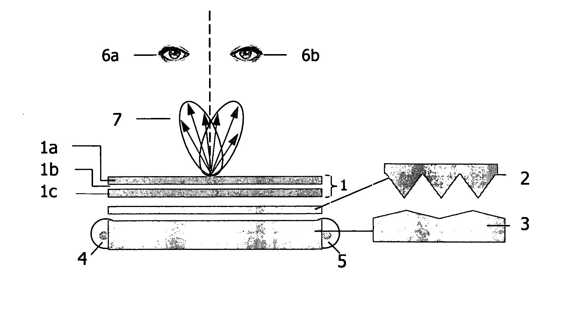
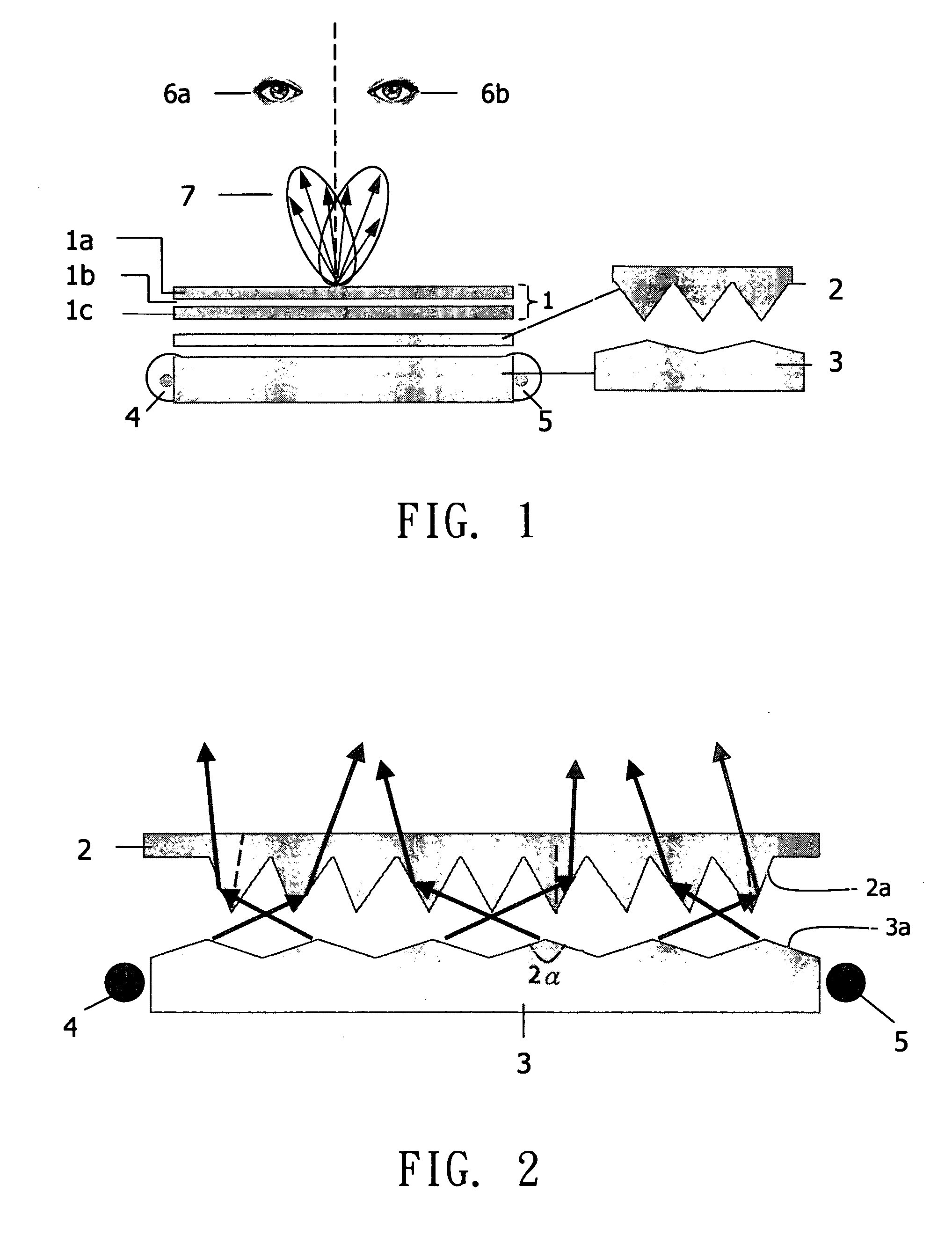
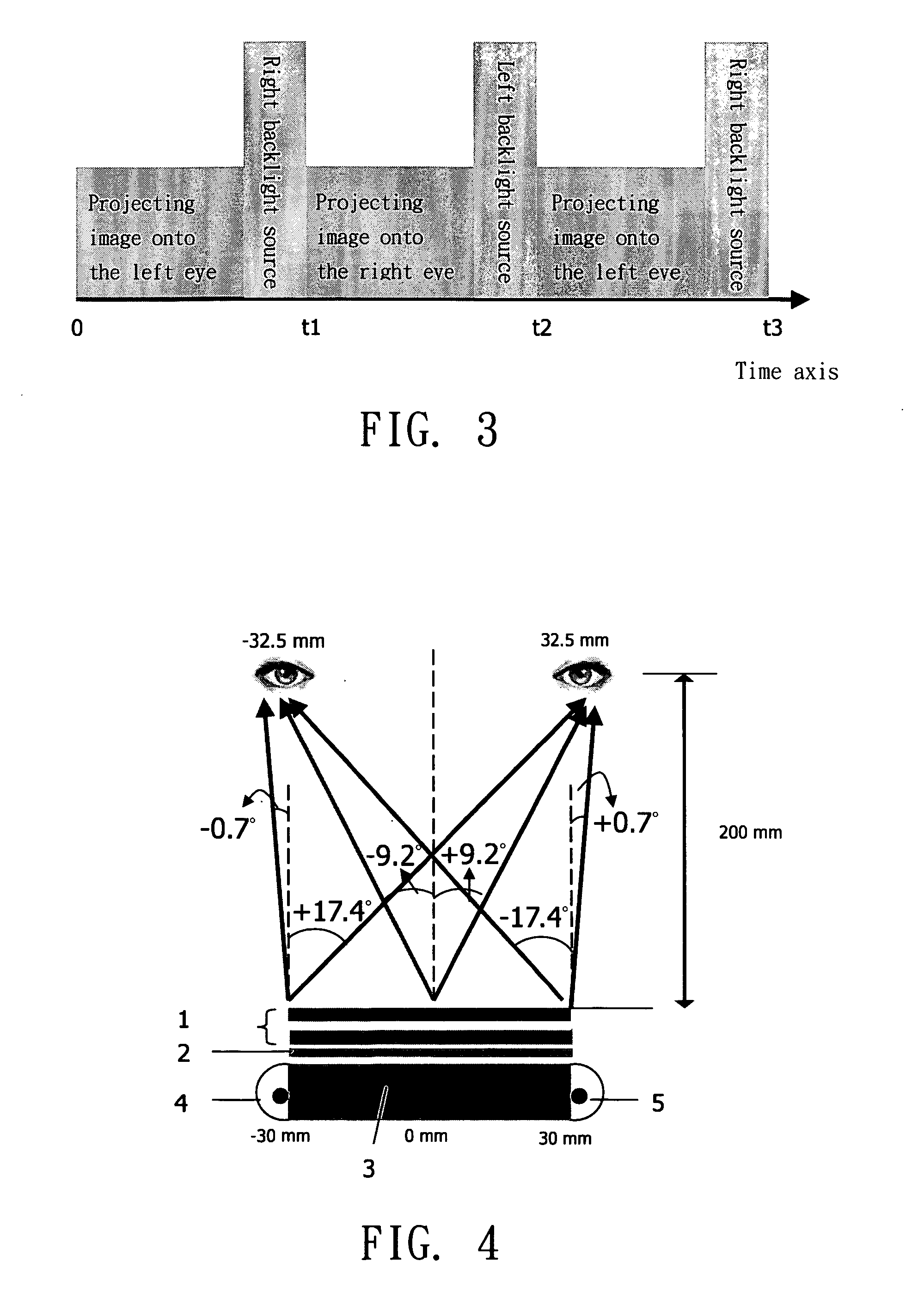
[0018] The image forming technique adopted in the present invention is a stereo-pair type 3D image forming technique. The 3D display system and the method thereof according the present invention directly uses the structural characteristics of internal elements of a backlight module and the time-multiplexed method so that the light, after emitting from the backlight module and passing through a liquid crystal layer, can be projected onto the left eye and the right eye respectively to present a 3D image.

[0019] Referring to FIG. 1, a structural diagram of a 3D display system according to a preferred embodiment of the present invention is shown. The 3D display system according to the present invention includes a liquid crystal display panel 1 and a directional backlight module. As shown in FIG. 1, the liquid crystal display panel 1 includes an first substrate 1a, a liquid crystal layer 1b and a second substrate 1c, wherein the liquid crystal layer 1b is sandwiched between the first sub...


PUM

PropertyMeasurementUnit
point angle 2αaaaaaaaaaa
widthaaaaaaaaaa
widthaaaaaaaaaa

Abstract

A three-dimensional (3D) display system includes a liquid crystal display and a directional backlight module. The backlight module disposed behind the liquid crystal display includes a light-guide plate, a focusing layer, a left backlight source, a right backlight source, and a first V-shaped micro-grooved and a second V-shaped micro-grooved structures of the light-guide plate. The focusing layer is disposed between the light-guide plate and the liquid crystal display. The 3D display method is to instantly switch on and off the left and the right backlight sources to alternately emit the light from the left side and right side of light-guide plate. By means of the first and the second V-shaped micro-grooved structure, the light transmitted from the light-guide plate is focused by the focusing layer within a particular range of angles and passing through the liquid crystal layer for being alternately projected to form a 3D image.

Description

[0001] This application claims the benefit of Taiwan application Serial No. 93114833, filed May 25, 2004, the subject matter of which is incorporated herein by reference. BACKGROUND OF THE INVENTION [0002] 1. Field of the Invention [0003] The present invention relates to a display system and a method thereof. More particularly to a three-dimensional (3D) display system and method thereof. [0004] 2. Description of the Related Art [0005] As the display technique of two-dimensional (2D) images getting matured, the display technique of 3D images will be a trend in next generation. The display of 3D image not only provides a better quality entertainment, but also has a wide range of application in all aspects of real life such as medical and military purposes. In real world, an image is interpreted as a 3D image via the binocular disparity of the brain. Artificial 3D image forming principle forms a 3D image by simulating the real situation or by projecting different image stereo pairs on...

Claims


Application Information

Patent Timeline
Patent Type & Authority Applications(United States)
IPC IPC(8): G02B30/33G02F1/1335G02F1/13357H04N13/00
CPCG02B27/225H04N13/0418G02F1/133615G02B27/2264H04N13/32G02B30/24G02B30/33
Inventor CHIEN, KO-WEISHIEH, HAN-PINGCHU, YU-MIOUNTSAI, CHING-YULIN, YUNG-LUNHU, CHIH-JENCHANG, CHIH-MINGHSU, YI-CHENGCHEN, PO-LUN
Owner AU OPTRONICS CORP
Why Eureka
Try Eureka