Light quantity adjusting device and projector apparatus using the same

a technology of light quantity and adjustment device, which is applied in the direction of picture reproducers, television systems, instruments using projection devices, etc., can solve the problems of difficult to obtain clear images, image looks too bright, and a risk of fatigue of eyes or optical stimulus, so as to reduce the operation sound of the blade members, reduce contact, and reduce frictional force

Inactive Publication Date: 2005-12-01
NISCA KK
View PDF4 Cites 31 Cited by
  • Summary
  • Abstract
  • Description
  • Claims
  • Application Information

AI Technical Summary

Benefits of technology

[0015] The substrate is provided with a blade guide surface for guiding the blade members to rotate. The blade guide surface is formed of an inclined surface or a step surface having a step in a direction perpendicular to the projection optical path. Accordingly, the blade members rotate along the blade guide surface in a state inclined by a predetermined angle with respect to the optical path. With the inclined state, a small gap is formed between the overlapped blades, thereby reducing frictional force. Accordingly, it is possible to reduce operation sound of the blade members and wear due to friction. The guide surface includes a first contact surface formed on the circumferential edge of the fulcrum pin for supporting the blade member at a high position and a second contact surface formed on the circumferential edge of the optical path opening for supporting the blade member at a low position.
[0016] In other words, the substrate is provided with the first and second contact surfaces positioned on a circle concentric with the optical path opening and having a step shape. The first contact surface guides the blade member in an inclined state with respect to the optical path direction at a position higher than the second contact surface does. As a result, the blade members arranged around the optical path opening with the predetermined spacing are overlapped at different positions from the fulcrum pins rotatably supporting the blade members. Accordingly, even if the first contact surface and the second contact surface for supporting the blade members are at an equal level, it is possible to reduce contact between the blade members or form a small gap therebetween.
[0017] A protrusion may be formed on the blame member for forming a small gap between the blade members. Accordingly, when the blade members are curved or deformed, it is still possible to form the small gap between the blade members, thereby reducing wear and operation sound.

Problems solved by technology

For example, when an image with low luminance is projected in a bright room, it is difficult to obtain a clear image.
In contrast, when an image with high luminance is projected in a dark room, the image looks too bright.
Further, when luminance of an image changes greatly and repeatedly for long time, i.e., from a dark screen to a bright screen, it is possible to pose a risk of fatigue of eyes or an optical stimulus.
In particular, when the projector apparatus for a presentation requiring high luminance is used for a home theater, an image becomes too bright and a user may suffer eye fatigue.
When an image becomes repeatedly bright and dark, for example, an image changes bright and dark for every one several tenth second, a viewer may suffer eye fatigue and receive an optical stimulus, thereby causing a physical problem.
However, the following problems may occur when such a structure widely known in a camera device, in which the plural blades arranged around the optical path opening and rotate to adjust an aperture of the optical path opening, is adopted in a projector apparatus such as a projector.
However, in the projector apparatus, when the light quantity adjusting blades are opened and closed (operated) and generate an operation sound, there may be a serious influence on an environment of a meeting or movie.
In particular, when the blade members are made of thin metal sheets, it is possible to generate a large metallic noise.
Accordingly, the operation sound of the blades is repeated all the time, thereby making a user uncomfortable.
When the blades are operated at a lower speed to reduce the noise, it is difficult to adjust the light quantity to a change in an image, thereby causing image flickering.

Method used


Image

  • Light quantity adjusting device and projector apparatus using the same
  • Light quantity adjusting device and projector apparatus using the same
  • Light quantity adjusting device and projector apparatus using the same

Examples


Embodiment Construction

[0033] Hereunder, embodiments of the present invention will be described with reference to the accompanying drawings.

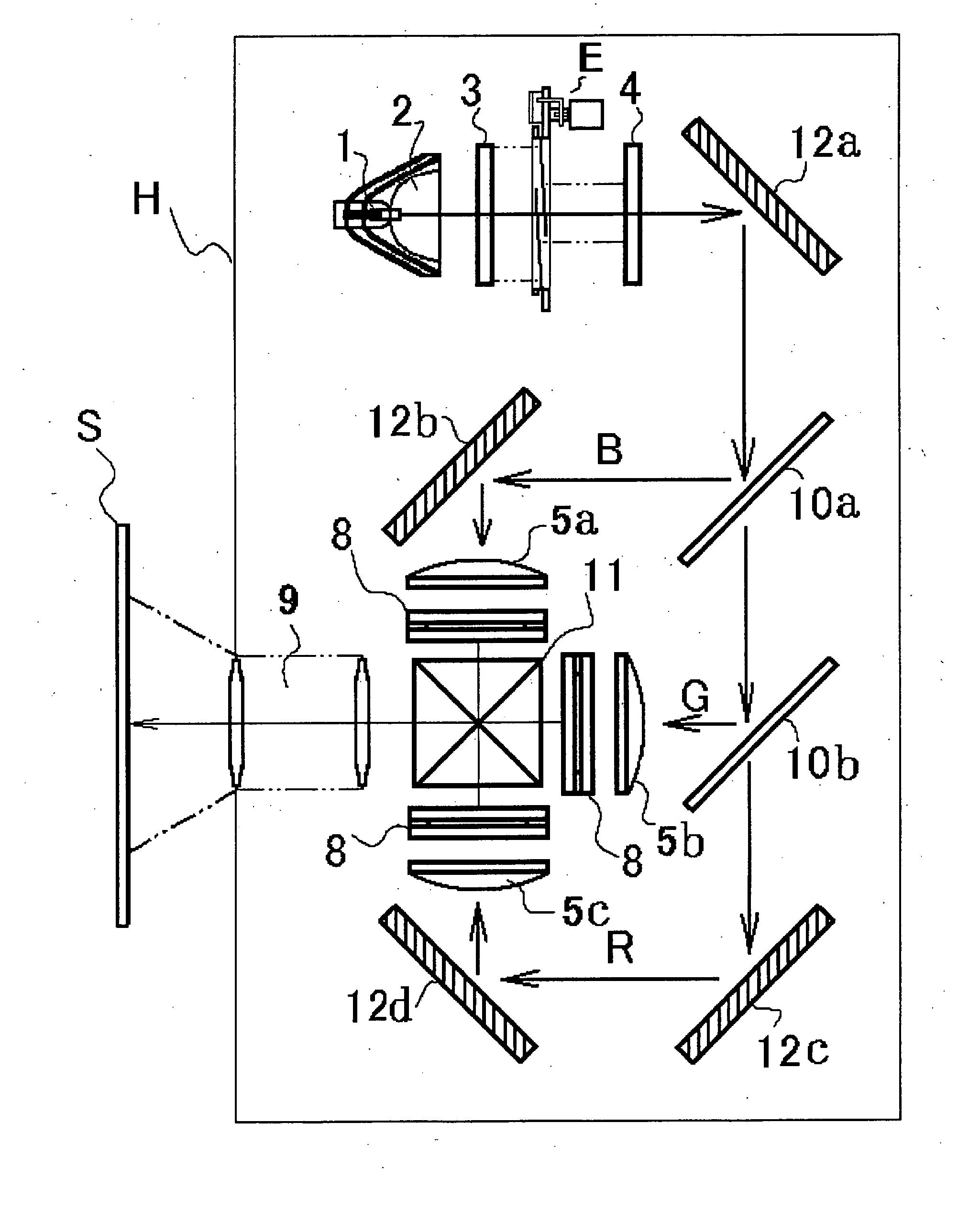
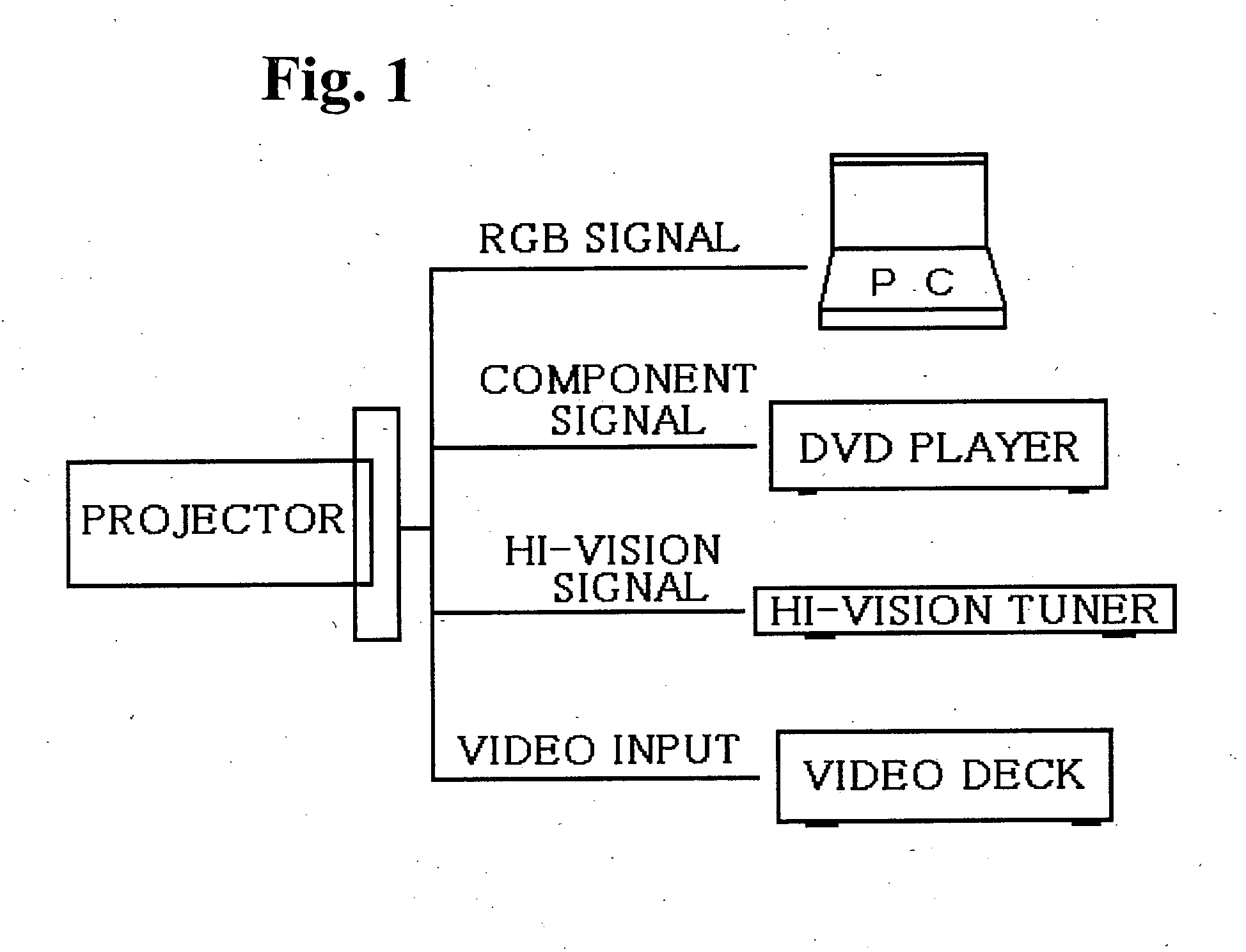
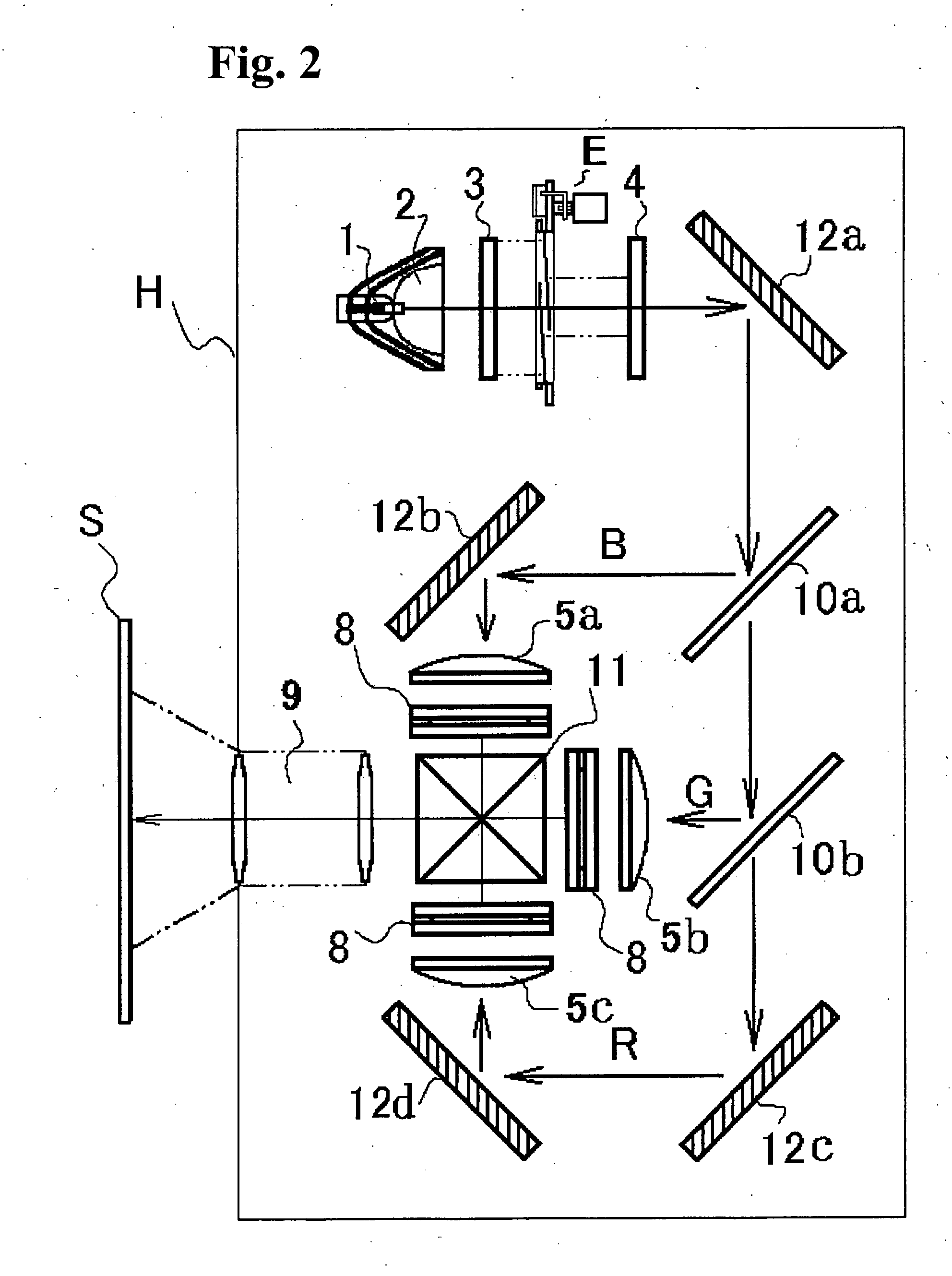
[0034] First, a projector apparatus provided with a light quantity adjusting device of the invention will be described. FIG. 1 is an explanatory diagram showing a system configuration of a projector apparatus according to an embodiment of the present invention, and FIG. 2 is a schematic diagram of the projector apparatus according to the embodiment of the present invention.

[0035] A method of inputting images to a projector employs RGB signals, component signals, Hi-Vision signals, video signals and so on. The RGB signals are transmitted from the image output terminal of a computer, for example, to the projector. The component signals are transmitted to a DVD player. The Hi-Vision signals are transmitted to a tuner such as a Hi-Vision TV. The video signals are transmitted from the output terminal of a video deck or the like to a projector device. As the projector dev...


PUM


Abstract

A light quantity adjusting device for adjusting light quantity of a projector apparatus. The adjusting device includes a substrate having an optical path opening and a blade guide surface having level differences in a direction perpendicular to the optical path; a plurality of blade members arranged at a circumferential edge of the optical path opening for rotating along the blade guide surface in an inclined state with respect to the optical path; and a plurality of pins disposed on the substrate for supporting base end portions of the blade members to rotate around the base end portions for opening and closing the optical path opening. A transmission member is mounted on the substrate for engaging the blade members, and a drive device drives the transmission member to rotate the blade members to open and close the optical path opening.

Description

BACKGROUND OF THE INVENTION AND RELATED ART STATEMENT [0001] The present invention relates to a light quantity adjusting device for adjusting brightness of an image when a light source irradiates an image formed by image forming means such as a Braun tube or a liquid crystal panel so that the image is projected on a screen through a projecting lens. The present invention also relates to a projector apparatus using the light quantity adjusting device. [0002] In a projector apparatus, an image such as a symbol and a picture is formed on an image forming unit such as a Braun tube (i.e., CRT) or a liquid crystal panel, and a light source such as a halogen lamp irradiates the image, so that a projecting lens projects the image on a screen. The projector apparatus projects a still image such as a symbol image on a screen for a presentation, or a motion picture on a screen of a home theater. [0003] When the projector apparatus is used for a presentation or movie, an environment significant...

Claims


Application Information

Patent Timeline
Patent Type & Authority Applications(United States)
IPC IPC(8): G03B21/14G03B21/20H04N5/58H04N5/74H04N9/31
CPCH04N5/58H04N5/74H04N9/3105H04N9/3155H04N21/4318G03B21/2053G03B21/2093G03B21/208H04N21/4122H04N9/3197G03B21/20
Inventor HARA, TOYOYUKISHIRASU, MASAHIDEHAYAKAWA, YUKIHIKO
Owner NISCA KK
Why Eureka
Try Eureka