Rack mounted computer system

a computer system and rack technology, applied in the direction of dismountable cabinets, electrical apparatus casings/cabinets/drawers, instruments, etc., can solve the problems of increasing the total cost of the system, affecting the positioning of components, and occupying a small space above the motherboard

Active Publication Date: 2005-12-01
HEWLETT-PACKARD ENTERPRISE DEV LP
View PDF26 Cites 107 Cited by
  • Summary
  • Abstract
  • Description
  • Claims
  • Application Information

AI Technical Summary

Benefits of technology

[0015] In accordance with embodiments of the present invention, a rack-mount computer is provided, comprising: a main board comprising a printed circuit board, at least one processor, and memory; and a computer chassis containing the main board, the computer chassis comprising: a fr

Problems solved by technology

However, the manual positioning and installation of each rail can be a time-consuming and labor-intensive process, significantly increasing the total cost of the system.
However, layout difficulties arise when trying to add the additional components which are either mounted onto or attached to the motherboard to form a functional computer.
Because of the low profile of the computer chassis, there is very little room above the motherboard for positioning these components.
However, the short height of the chassis limits the number and size of components that can be placed here.
The dense packing of components in these low-profile computer chassis presents cooling problems as well.
Because the 1U computer chassis are so thin, any component contained within the computer chassis can significantly impede the flow of air through the computer chassis and across all of the components.
This airflow problem can

Method used


Image

  • Rack mounted computer system
  • Rack mounted computer system
  • Rack mounted computer system

Examples


Embodiment Construction

[0034] In the following description, reference is made to the accompanying drawings which illustrate several embodiments of the present invention. It is understood that other embodiments may be utilized and mechanical, compositional, structural, electrical, and operational changes may be made without departing from the spirit and scope of the present disclosure. The following detailed description is not to be taken in a limiting sense, and the scope of the embodiments of the present invention is defined only by the claims of the issued patent.

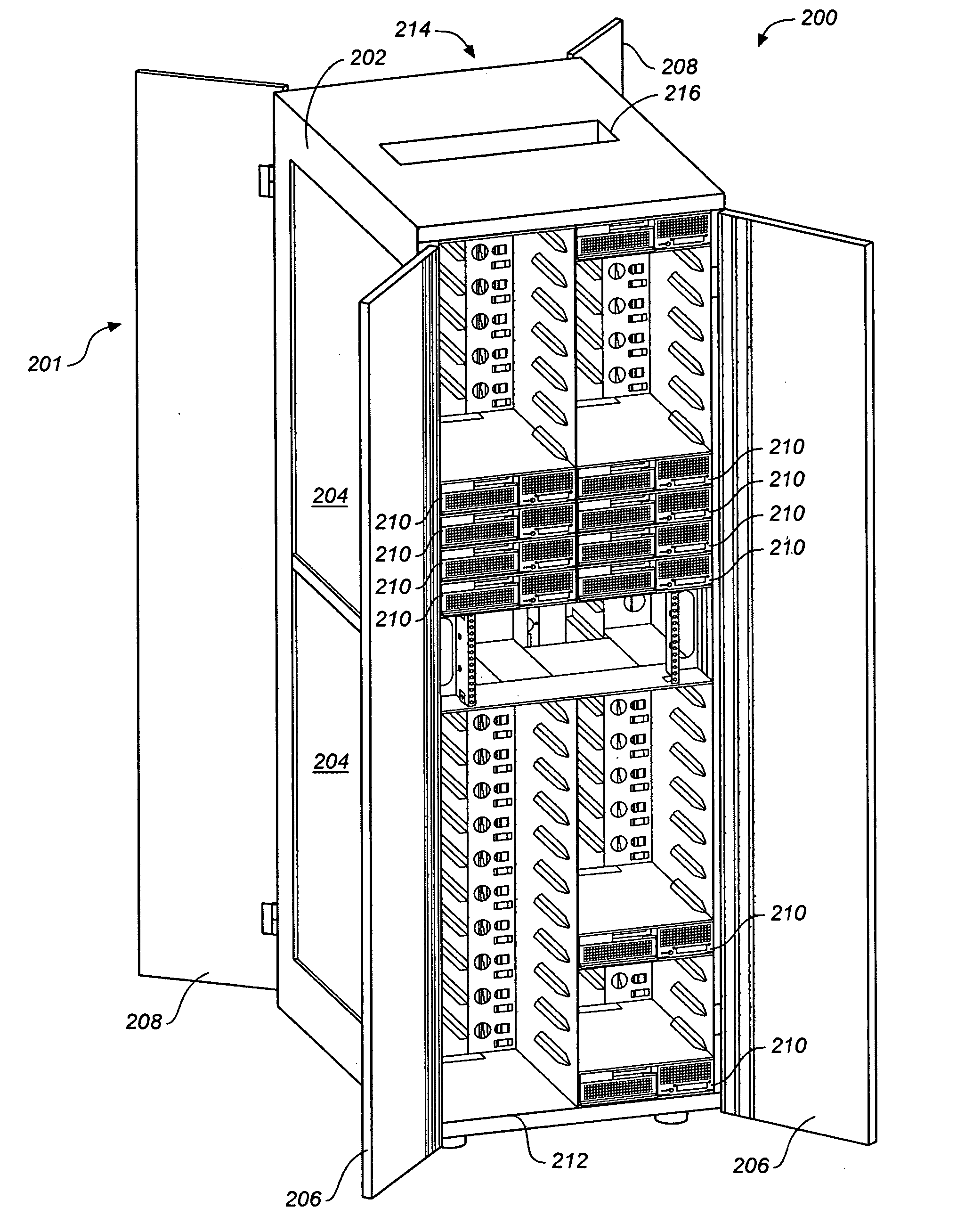
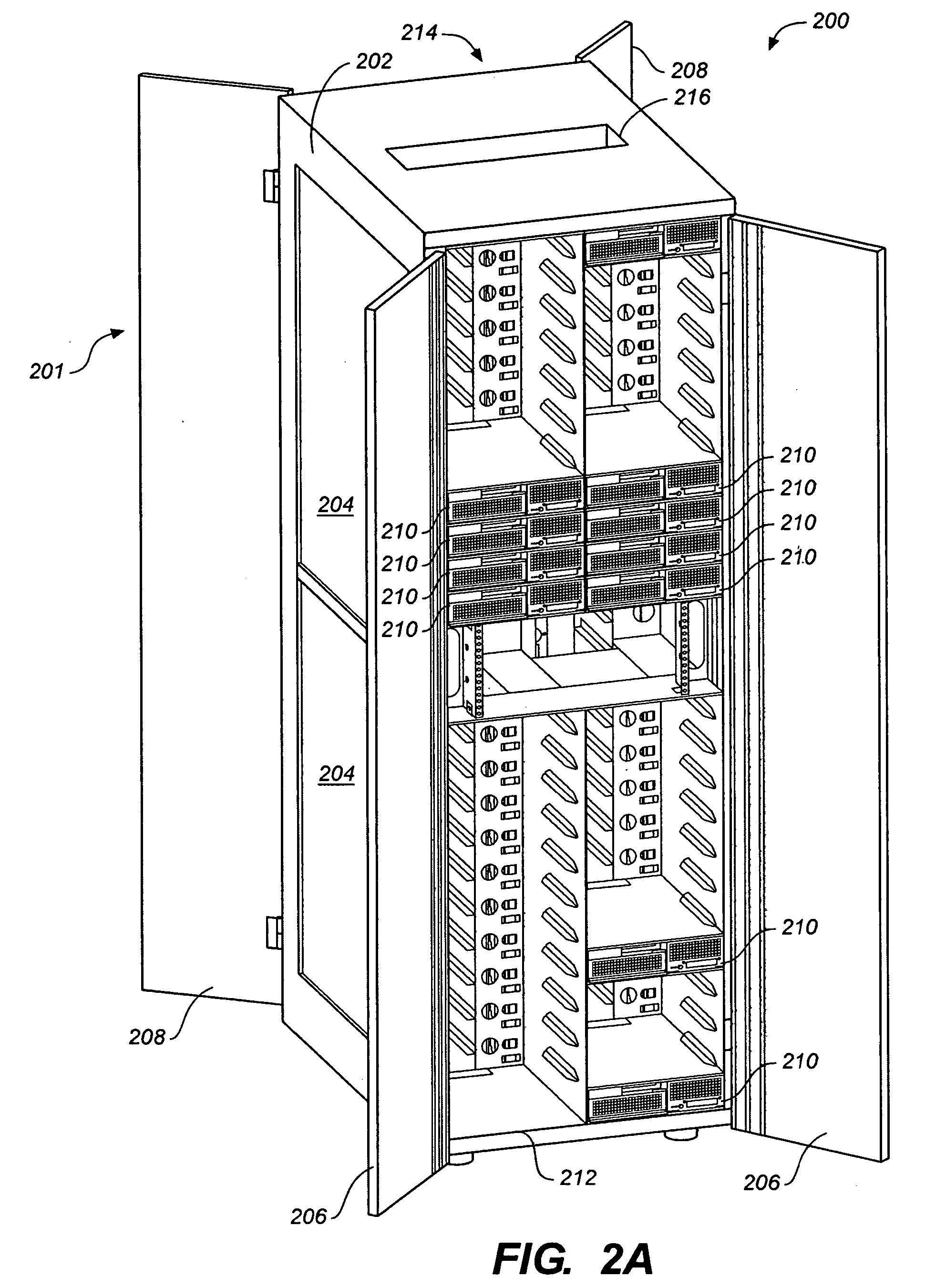
[0035]FIG. 2A shows a rack-based computer system 200 in accordance with embodiments of the present invention. FIG. 2B is an enlarged view of a portion of the computer system 200. The computer system 200 comprises a rack assembly 201 which provides the structural support for a plurality of computers 210 contained therein.

[0036] The rack assembly 201 may comprise a vertically elongated, floor mounted cabinet assembly. The rack assembly 201 may ...


PUM


Abstract

A rack mounted computer system. In one variation the computer rack is configured for side-by-side placement of computers. In another variation, the computer rack includes flanges for supporting the placement of computer units within the rack. In another variation the computer rack is configured with retaining clips. In yet another variation, the computer rack is configured to receive computers with chassis that are adapted for side-by-side placement.

Description

CROSS-REFERENCE TO RELATED APPLICATION [0001] This application claims the benefit of U.S. provisional patent application No. 60 / 569,025, entitled “RACK MOUNTED COMPUTER SYSTEM” filed on May 7, 2004, U.S. provisional patent application No. 60 / 568,969 entitled “INTERFACE ASSEMBLY”, filed May 7, 2004; U.S. provisional patent application No. 60 / 569,020 entitled “ELECTROMAGNETIC INTERFERENCE SHIELD FOR I / O PORTS”, filed May 7, 2004; and U.S. provisional patent application No. 60 / 569,019 entitled “DIRECTIONAL FAN ASSEMBLY”, filed May 7, 2004, each of which is incorporated herein by reference in it entirety.BACKGROUND [0002] As information technology has rapidly progressed, computer network centers such as server farms and server clusters have become increasingly important to our society. The server farms provide efficient data processing, storage, and distribution capability that supports a worldwide information infrastructure, which has come to dominate how we live and how we conduct our...

Claims


Application Information

Patent Timeline
IPC IPC(8): H05K5/00H05K7/14
CPCH05K7/1488G06F1/183
Inventor COGLITORE, GIOVANNICASEBOLT, MATTHEW P.
Owner HEWLETT-PACKARD ENTERPRISE DEV LP
Why Eureka
Try Eureka