Transmission apparatus and receiving apparatus

a technology of receiving apparatus and transmission apparatus, applied in the field of radio communication, can solve the problems of sacrificing power efficiency, affecting the transmission quality, and unwanted emission to outside the band, and achieve the effect of reducing the papr of the ofdm radio signal

Inactive Publication Date: 2005-12-01
NTT DOCOMO INC
View PDF6 Cites 83 Cited by
  • Summary
  • Abstract
  • Description
  • Claims
  • Application Information

AI Technical Summary

Benefits of technology

[0019] The present invention is contrived to solve at least one of the above-mentioned problems. An object of the present invention is to

Problems solved by technology

If the power amplifier (PA) operates in the non-linear region, there may arise problems such as degraded transmission quality, and unwanted emission to outside of the band.
A power amplifier having a wide liner region may be used, but it sacrifices power efficiency.
However, the pre-distortion scheme clips a part of a signal having a peak power level exceeding a saturation region of the amplifier.
In the method in which an unwanted peak power value is clipped, orthogonality among sub-carriers collapses, so that interference between symbols increases and receiving quality may be degraded.
With regard to the PTS method, it is necessary to perform complex multiplication for each signal series when supplying a weight to each signal so that complexity increases.
This problem is disadvantageous especially for

Method used


Image

  • Transmission apparatus and receiving apparatus
  • Transmission apparatus and receiving apparatus
  • Transmission apparatus and receiving apparatus

Examples


first embodiment

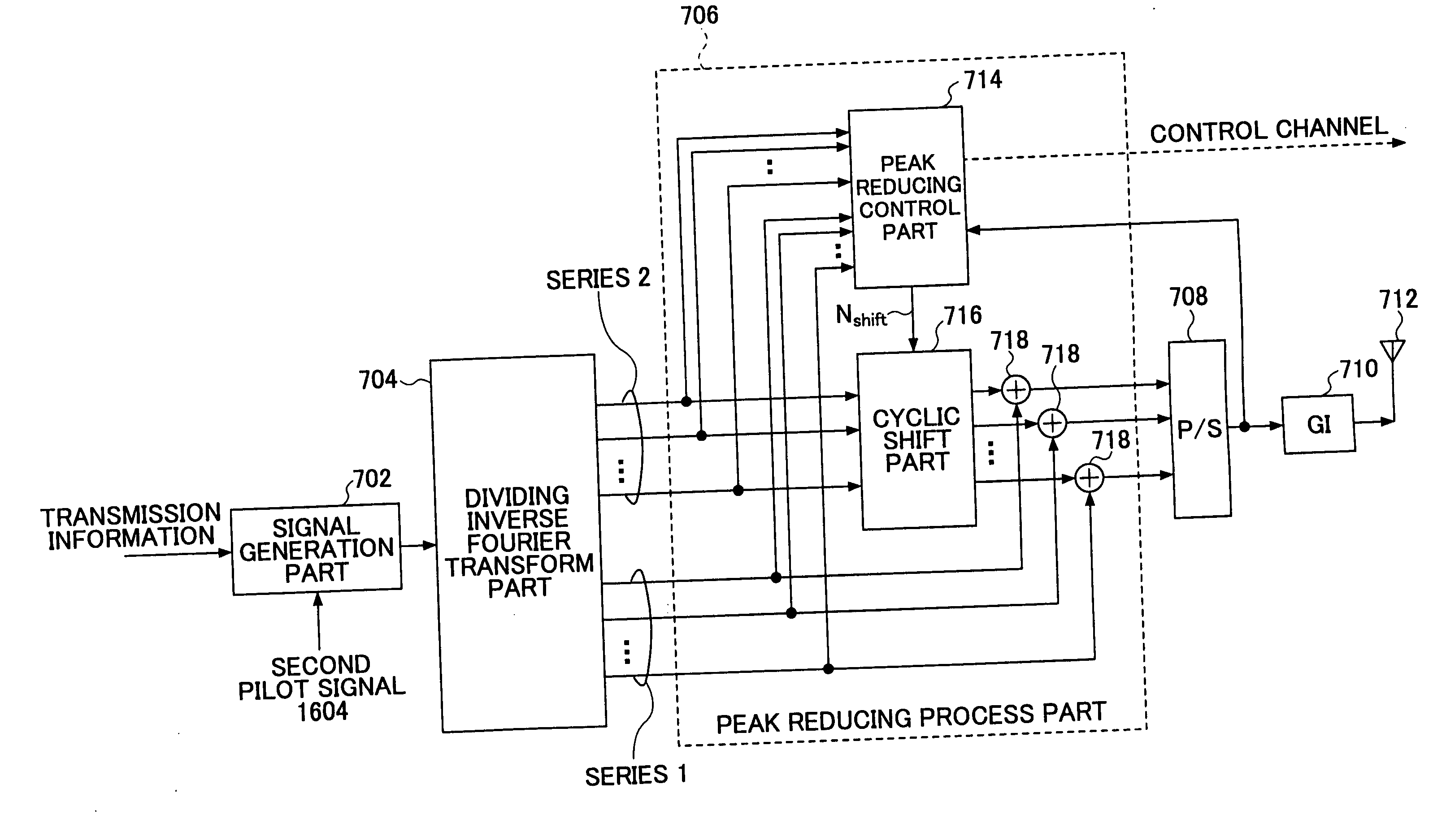
[0060]FIG. 7 is a partial block diagram showing a part of the transmission apparatus according to an embodiment of the present invention. The transmission apparatus includes a signal generation part 702, a dividing inverse Fourier transform part 704, a peak reducing process part 706, a parallel-serial conversion part (P / S) 708, a guard interval adding part 710, and an antenna 712. The peak reducing process part 706 includes a peak reducing control part 714, a cyclic shift part 716 and plural synthesizing parts 718.

[0061] The signal generation part 702 receives a bit sequence indicating transmission information, and generates signal information corresponding to each sub-carrier so as to output the signals as a signal series.

[0062] As shown in FIG. 8 in detail, the dividing inverse Fourier transform part 704 receives a signal, and outputs a signal series 1 and a signal series 2 as two signal groups on which inverse Fourier transform has been performed. In the present embodiment, alt...

second embodiment

[0101] In the following, some embodiments are described in a case where the transmission apparatus does not directly send data indicating cyclic shift information to the receiving apparatus. In an embodiment, a pilot signal used for channel estimation is OFDM-converted as described in the first embodiment. That is, the pilot signal is supplied to the dividing inverse Fourier transform part 704 (FIG. 7), signal series are combined such that PAPR is reduced in the cyclic shift part 716 and the synthesizing part 718, and the signals are transmitted. In FIG. 7, the pilot signal is represented as a second pilot signal, and examples of using a first pilot signal and a second pilot signal are described later. The pilot signals are transmitted with a signal format shown in FIG. 13, for example. In the figure, “f” indicates a frequency direction, and “t” indicates a time direction. In the example shown in the figure, pilot signals are inserted to all sub-carriers in a time slot. A region enc...

third embodiment

[0112]FIG. 19 is a partial block diagram of a transmission apparatus according to an embodiment of the present invention. The transmission apparatus includes a signal generation part 1902, a dividing inverse Fourier transform part 1904, a peak reducing control part 1906, a cyclic shift part 1916, plural multiplying parts 1922, plural synthesizing parts 1918, a parallel-serial transform part (P / S) 1908, a guard interval adding part 1910 and an antenna 1912.

[0113] The signal generation part 1902 receives transmission information, and forms signal information corresponding to each sub-carrier so as to output a signal series.

[0114] The dividing inverse Fourier transform part 1904 is almost similar to one described with reference to FIG. 8. The dividing inverse Fourier transform part 1904 receives a signal, and outputs a signal series 1 and a signal series 2 as two signal groups on which inverse Fourier transform has been performed.

[0115] The peak reducing control part 1906 outputs cy...


PUM


Abstract

A transmission apparatus used in a radio communication system adopting the OFDM scheme is disclosed. The transmission apparatus includes: a dividing inverse Fourier transform part including plural transform parts, wherein the dividing inverse Fourier transform part divides a signal to be transmitted into plural signals, and each of the plural transform parts performs inverse Fourier transform on one of the plural signals; a peak control part for outputting a peak control signal based on peaks that are detected from output signals of the dividing inverse Fourier transform part; and a peak reducing process part for adjusting a weight or an arranging order of an output signal of the dividing inverse Fourier transform part according to the peak control signal to output an adjusted signal, and synthesizing the adjusted signal with other signal so as to output a synthesized signal.

Description

BACKGROUND OF THE INVENTION [0001] 1. Field of the Invention [0002] The present invention relates to the field of radio communications. More particularly, the present invention relates to a transmission apparatus and a receiving apparatus that adopt the OFDM (Orthogonal Frequency Division Multiplexing) scheme. [0003] 2. Description of the Related Art [0004] The OFDM scheme, which is getting attention in the field of radio communications, is a technology for realizing good signal transmission even under a multipath transmission environment by arranging plural carriers (sub-carriers) at intervals of a frequency such that the plural carriers are orthogonal to each other. In a transmission apparatus in this scheme, as shown in FIG. 1 briefly, a source signal is generated in a signal generation part based on transmission information. The signal is converted to a parallel signal series by a serial-parallel conversion part (S / P), processed by an inverse fast Fourier transform part (IFFT pa...

Claims


Application Information

Patent Timeline
IPC IPC(8): H04J11/00H04L25/02H04L27/26
CPCH04L25/0226H04L25/0232H04L27/2624H04L27/2614H04L27/2621H04L27/2613H04L27/26134
Inventor SHEN, JIYUNFUJII, HIROMASAASAI, TAKAHIROSUDA, HIROHITO
Owner NTT DOCOMO INC
Why Eureka
Try Eureka