Method and device for increasing patient safety in clinical scanners

Inactive Publication Date: 2005-12-01
SIEMENS AG
View PDF5 Cites 42 Cited by
  • Summary
  • Abstract
  • Description
  • Claims
  • Application Information

AI Technical Summary

Benefits of technology

[0006] An object of the present invention is to provide a method that ensures optimal positions of a patient in an examination apparatus without the ov

Problems solved by technology

Such an automatic monitoring is important because it is not sufficient that operating personnel of the scanner correctly position the patient at the beginning with the extremities properly arranged so that the cited contacts are prevented.
Because such examinations can frequently be of long duration, it cannot be precluded that the patient (for whom a long-durati

Method used


Image

  • Method and device for increasing patient safety in clinical scanners
  • Method and device for increasing patient safety in clinical scanners
  • Method and device for increasing patient safety in clinical scanners

Examples


Embodiment Construction

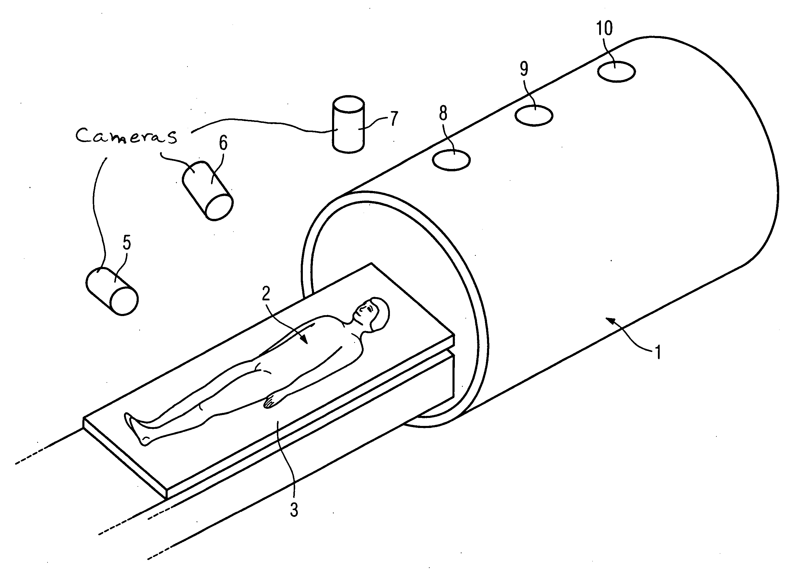
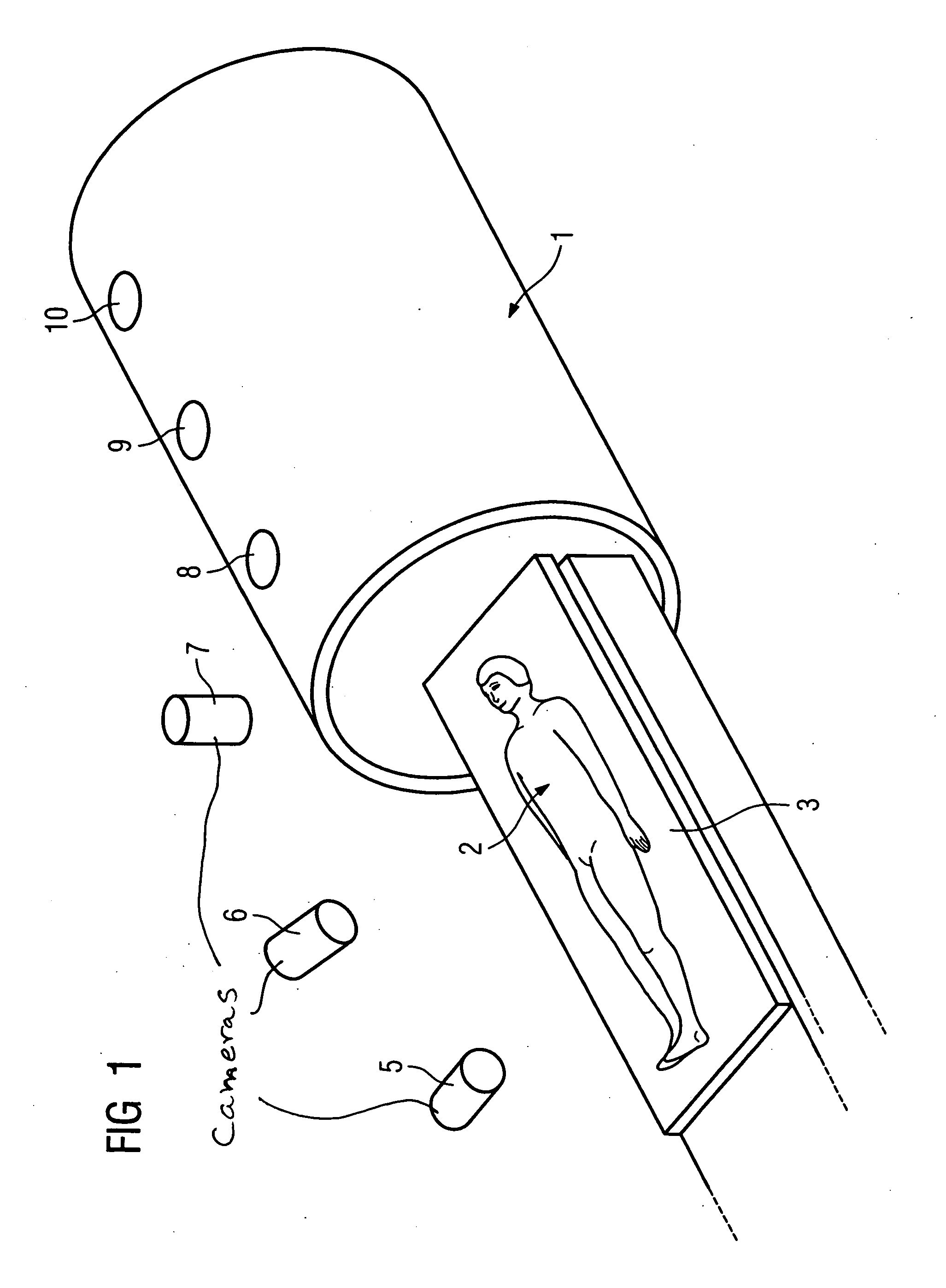
[0014] In FIG. 1, a scanner tube 1 can be seen (for example for an MR scanner) into which a patient 2 can be inserted on a movable patient bed 3.

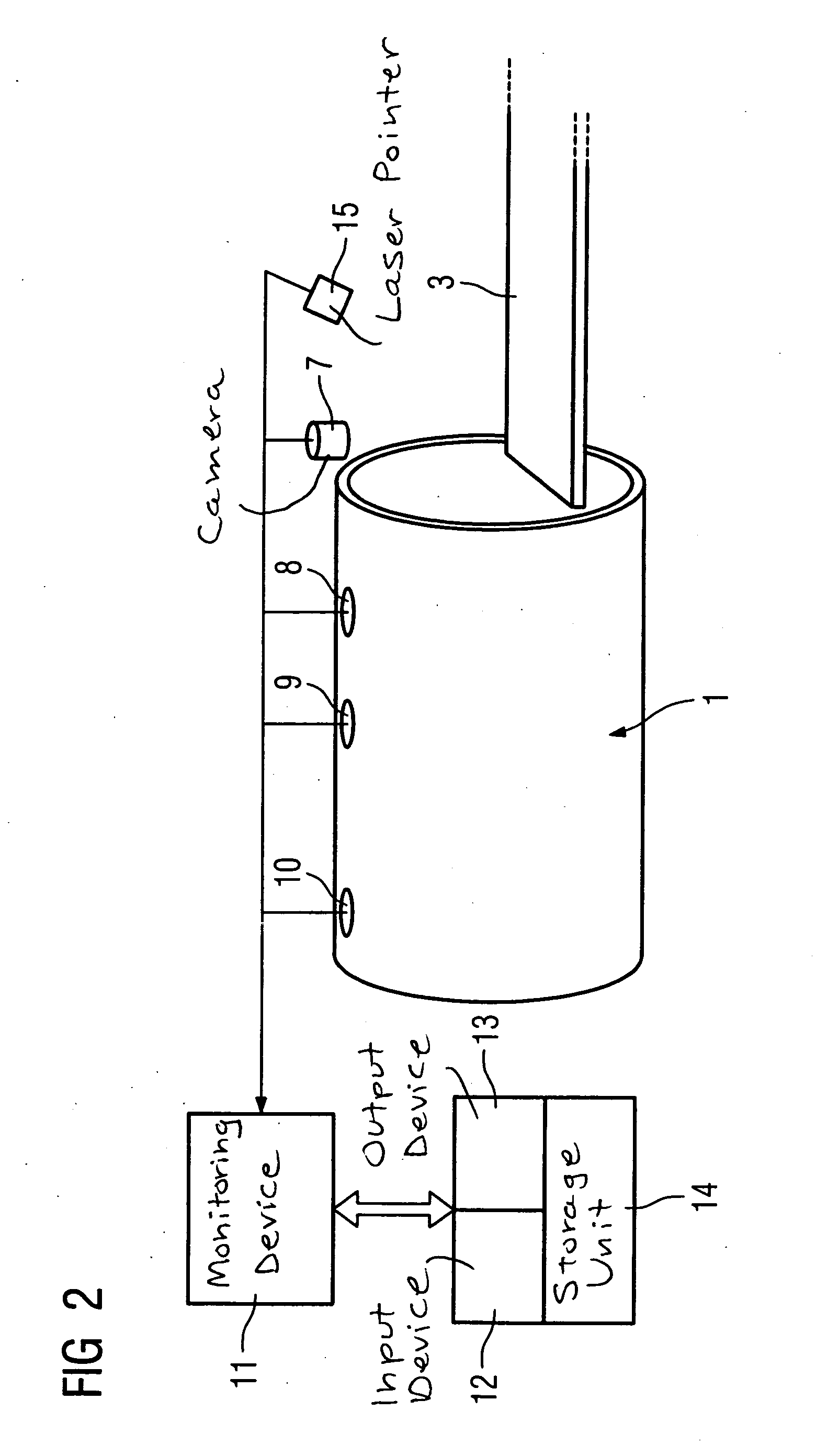
[0015] Some cameras for a 3D image system are shown at 5, 6 and 7, with which observation of the patient can ensue outside of the scanner tube 1. A 3D image system for monitoring the interior of the scanner tune 1 also can be formed by cameras that can be introduced into the interior through openings 8, 9 and 10. Further cameras at the head end are directed inwardly. Incorrect positioning of the patient (as shown in FIGS. 3a through 3d) are detected by this camera system and corrected by a suitable re-arrangement of the patient. These are positions in which extremities contact one another or contact the body trunk to form electrical current loops, such that pain or even serious adverse health effects could occur in the examination due to current flow in the patient's body. The 3D image camera system can identify the acquired images in term...


PUM


Abstract

In a method and device for increasing patient safety in clinical scanners, the positioning of the patient during the preparation and the implementation of the examination is monitored by a 3D camera system, and incorrect positions are automatically detected by comparison of the current image with standard specifications, and corresponding corrections are prompted.

Description

BACKGROUND OF THE INVENTION [0001] 1. Field of the Invention [0002] The present invention concerns a method and device for optimization of the use of clinical scanners with increased patient safety [0003] 2. Description of the Prior Art [0004] Achieving an optimized arrangement of a patient in a clinical scanner, for example an MR scanner, is of decisive importance for the success of an examination. For example, it depends on whether the patient is inserted into the scanner in the correct bearing and in the correct position (head first or feet first). Given the absence of an optimal alignment is possible, the patient must be moved out again and be positioned differently, which means a significant time expenditure that—in view of the cost of approximately $30 per operational minute of such a scanner—detracts significantly from the “bottom line” and can be decisive for the cost-effectiveness of the operation of such a scanner. [0005] It is even more decisive that, for many examination...

Claims


Application Information

Patent Timeline
IPC IPC(8): A61B5/055A61B6/00A61B19/00G01N23/00G01R33/28
CPCG01R33/283A61B5/0555A61B5/055A61B5/70
Inventor HAIDER, SULTAN
Owner SIEMENS AG
Why Eureka
Try Eureka