Image forming apparatus

a technology of forming apparatus and forming sheet, which is applied in the direction of electrographic process apparatus, instruments, optics, etc., can solve the problems of deterioration of image fixation performance, inability to store a number of sheets that can be stacked, and increase in the amount of curls, so as to reduce the deterioration of sheet stacking ability

Inactive Publication Date: 2005-12-01
KONICA MINOLTA INC
View PDF8 Cites 29 Cited by
  • Summary
  • Abstract
  • Description
  • Claims
  • Application Information

AI Technical Summary

Benefits of technology

[0007] An object of the present invention is to provide an image forming apparatus that is capable of reducing deterioration in sheet stacking ability on an ejected-paper tray by restraining amounts of curl of paper sheets while maintaining a fixation performance.

Problems solved by technology

An increase in amount of the curl deteriorates condition of the stacking, when a large number of sheets are stacked and stored on the ejected-paper tray, and thus may make it impossible to store a number of sheets that can be stacked and stored on condition that the amount of the curl is small.
The decrease in the fixation temperature of a fixing device as in the image forming apparatus disclosed in the publication, however, causes another problem of deterioration in image fixation performance.

Method used


Image

  • Image forming apparatus
  • Image forming apparatus
  • Image forming apparatus

Examples


Embodiment Construction

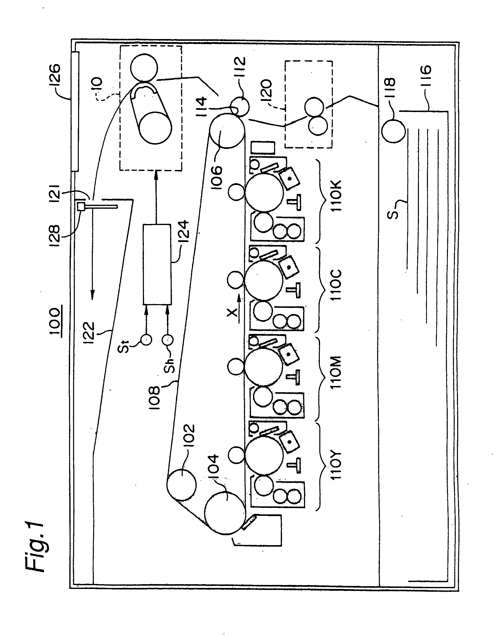
[0066]FIG. 1 is a schematic diagram of an image forming apparatus 100 that is an embodiment of the invention. The image forming apparatus 100 has an intermediate transfer belt 108 that is supported by three rollers 102, 104, and 106 and that is driven to rotate in a direction of an arrow X.

[0067] Under the intermediate transfer belt 108 are aligned image forming units 110Y, 110M, 110C, and 110K corresponding to yellow (Y), magenta (M), cyan (C), and black (K) toner. Toner images with the four colors can be formed and superposed on the intermediate transfer belt 108 by the image forming units 110Y, 110M, 110C, and 110K.

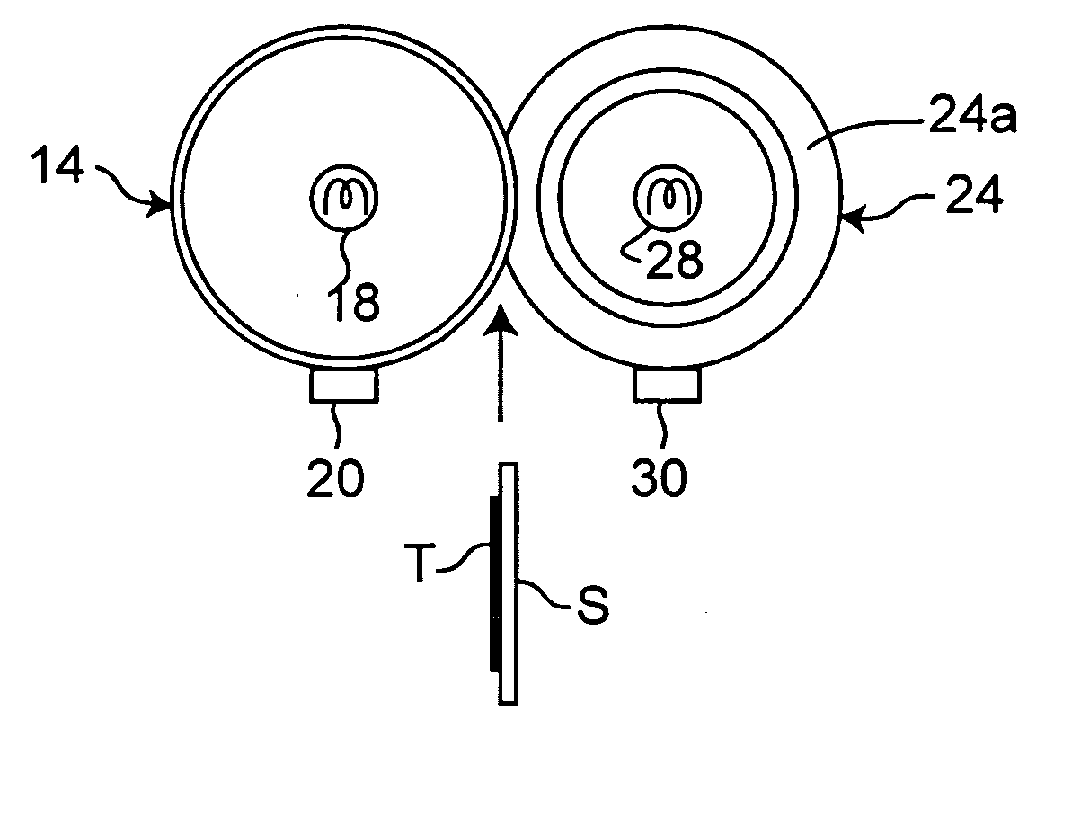
[0068] A transfer roller 112 is placed so as to be in contact with part of the intermediate transfer belt 108 that is supported by the roller 106. A transfer region 114 is formed between the transfer roller 112 and the intermediate transfer belt 108.

[0069] In a lower section of the image forming apparatus 100 is provided a paper feeding cassette 116 containing paper...


PUM


Abstract

An image forming apparatus has a heating rotator 12 that is heated by a first heat source 18, a pressurizing rotator 24 that is heated by a second heat source 28, that is in pressure contact with the heating rotator 12, and that forms a fixing nip 26 between the pressurizing rotator 24 and the heating rotator 12, a temperature sensor St that detects a temperature in the apparatus, and a controller 124 that controls temperatures of the heating rotator 12 and of the pressurizing rotator 24 by on-off control over the first heat source 18 and the second heat source 28, respectively, and that sets the temperature of the pressurizing rotator 24 higher than a normal temperature on condition that the temperature detected by the temperature sensor St exceeds a specified value.

Description

RELATED APPLICATION [0001] This application is based on Japanese Patent Application No.2004-161365, the content of which is incorporated herein by reference. BACKGROUND OF THE INVENTION [0002] The present invention relates to an image forming apparatus in a copying machine, a printer, a facsimile, a compound machine of those or the like. [0003] In conventional image forming apparatus of electrographic type, a paper sheet having an unfixed toner image formed on a surface thereof is passed through a fixing device, and the toner image is thereby heated and fused to be fixed on the sheet, which is thereafter ejected from the image forming apparatus and is stacked and stored on an ejected-paper tray. [0004] When the sheet is passed through the fixing device, curl is given to the sheet by influence of heat transferred to the sheet. An increase in amount of the curl deteriorates condition of the stacking, when a large number of sheets are stacked and stored on the ejected-paper tray, and t...

Claims


Application Information

Patent Timeline
Patent Type & Authority Applications(United States)
IPC IPC(8): G03G15/20
CPCG03G2215/2016G03G2215/2009G03G15/2039G03G2215/2038
Inventor OTSUKA, YUTAKA
Owner KONICA MINOLTA INC
Why Eureka
Try Eureka