
Shielded-conductor cable fixing construction

a shielding member and cable fixing technology, applied in the direction of coupling protective earth/shielding arrangement, coupling device connection, electrical equipment, etc., can solve the problems of braided conductor b>, high shielding performance cannot be obtained, shielding member b>31/b> easily falling off the shield shell, etc., to achieve high shielding performance, low cost, and high shielding properties

Active Publication Date: 2005-12-01
YAZAKI CORP
View PDF5 Cites 57 Cited by
  • Summary
  • Abstract
  • Description
  • Claims
  • Application Information

AI Technical Summary

Benefits of technology

[0010] The invention was made in view of the situations and an object thereof is to provide a shielded-conductor cable fixing construction which can enable the securing of high shielding properties and the strong and rigid fixing of the braided conductor to the shield shell at low costs without a need for making dense the interstices of the braided conductor.
[0016] According to the invention, the securing of high shielding properties and the strong and rigid fixing of the braided conductor to the shield shell can be enabled at low costs without a need for making dense the interstices of the braided conductor.
[0017] In addition, the securing of high shielding properties and the strong and rigid fixing of the braided conductor to the shield shell can be enabled at low costs without a need for making dense the interstices of the braided conductor. In addition, the braided conductor can be folded over on itself on the inside diameter side of the open end portion in an ensured fashion at a predetermined position of the open end portion, thereby making it possible to enable the fixing of the braided conductor to the shield shell in a more ensured fashion.

Problems solved by technology

In addition, since the friction between the terminal portion of the shielding member 31 and the shield shell 32 becomes small, the fixing force of the shielding member 31 to the shield shell 32 becomes weak, leading to a problem that the shielding member 31 easily comes off the shield shell 32.
Due to this, as with the related equipment shield connector 30 shown in FIGS. 5 and 6, not only the high shielding performance cannot be obtained but also the fixing force of the braided conductor 41 to the shield shell 42 becomes weak, leading to a problem that the braided conductor 41 easily comes off the shield shell 42.
In order to have dense interstices at the terminal portion of the shielding member or the open end portion of the braided conductor, however, there has been a problem that tremendous amounts of costs and time are needed to produce shielding members or braided conductors.
Due to this, a post-treatment such as of cutting the sharply pointed distal end portion of the shielding member 31 or the braided conductor 41 becomes necessary, leading to a problem that the production costs are increased.

Method used


Image

  • Shielded-conductor cable fixing construction
  • Shielded-conductor cable fixing construction
  • Shielded-conductor cable fixing construction

Examples


Embodiment Construction

[0026] Hereinafter, an embodiment of a shielded-conductor cable fixing construction according to the invention will be described based on FIGS. 1 to 4.

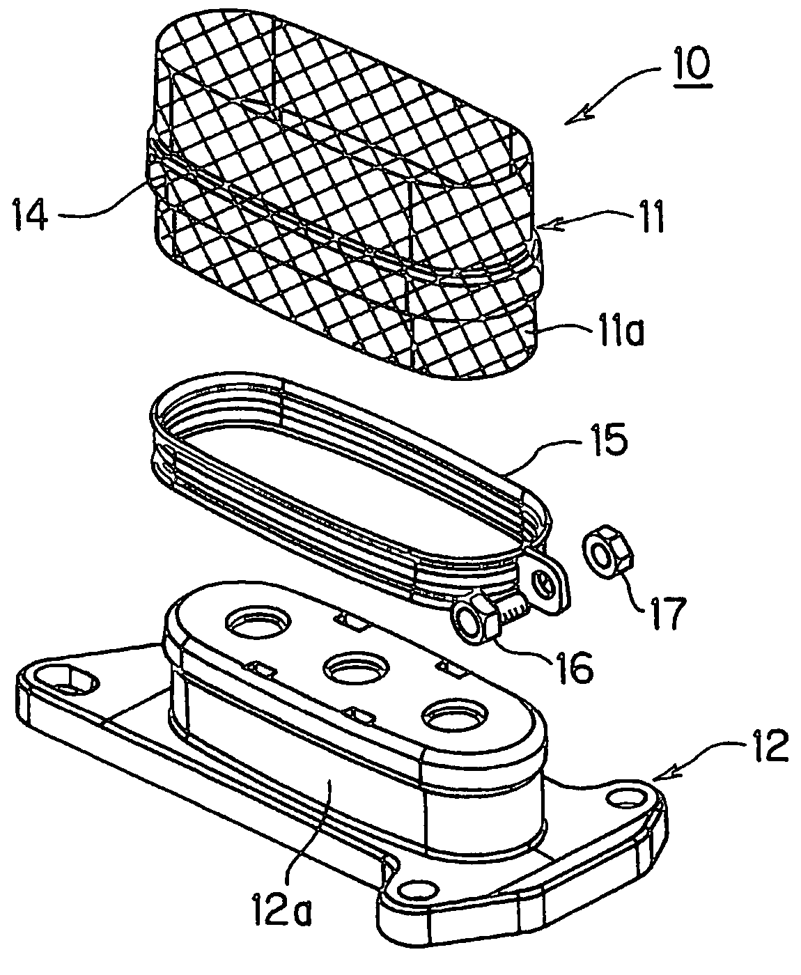
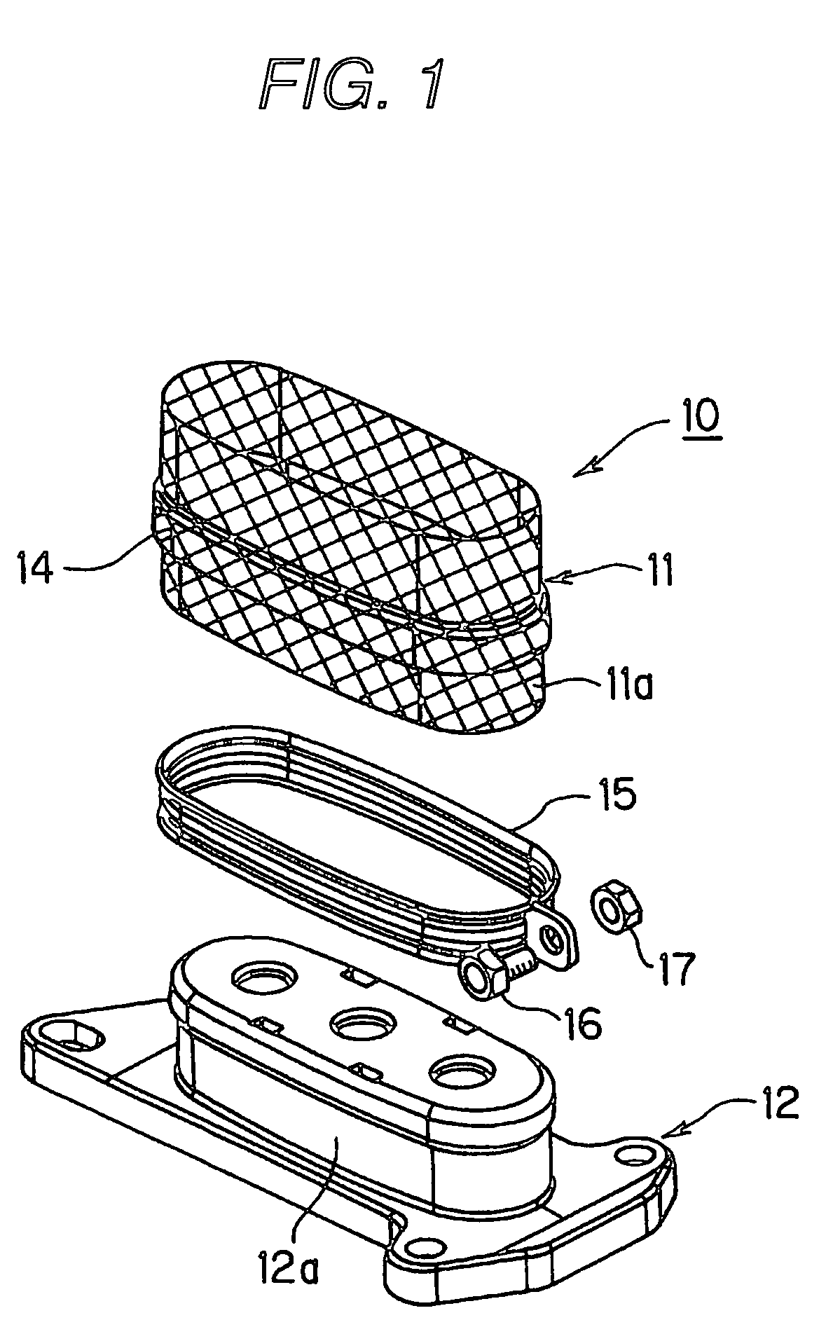
[0027]FIG. 1 is an exploded perspective view showing a shielded-conductor cable fixing construction according to an embodiment of the invention, FIG. 2 is an exploded perspective view showing a state of the shielded-conductor cable fixing construction shown in FIG. 1 before clamping by dice is carried out thereon, FIG. 3 is a schematic sectional view of a main portion of the shielded-conductor cable fixing construction shown in FIG. 1 which shows an open end portion of a braided conductor thereof, and FIG. 4 is a side view of a shield shell of the shielded-conductor cable fixing construction shown in FIG. 1.

[0028] Referring to FIGS. 1 to 4, in a shielded-conductor cable fixing construction, a shielded-conductor cable 10 is constructed such that a plurality of insulated electric wires (not shown) are covered with a tubular braided co...


PUM


Abstract

A braided conductor of a shielded-conductor cable is fitted on a ring of a shield shell in such a manner as to expand an inside diameter thereof in such a state that a portion of an open end portion of the braided conductor is folded over on itself on an inside diameter side of the open end portion so as to be doubled inwards and an annular member is held in the doubled portion of the open end portion.

Description

BACKGROUND OF THE INVENTION [0001] The present invention relates to a shielded-conductor cable fixing construction in which an insulated electric wire is covered with a tubular braided conductor and an open end portion of the braided conductor is fitted on a shield shell in such a manner as to expand an inside diameter of the braided conductor at the open end portion so that the braided conductor is connected to the shield shell. [0002] Some fixing constructions for shielded-conductor cables have been known (for example, refer to Patent Document 1). FIGS. 5 and 6 are both perspective views showing an equipment shield connector disclosed in Patent Document 1. [0003] As shown in FIGS. 5 and 6, in an equipment shield connector 30, a shielding member 31 encloses a plurality of electric wires (not shown) altogether therein and is fixed to a shield shell 32 at a terminal portion thereof so as to be connected to a shield case (not shown) via the shield shell 32. The terminal portion of the...

Claims


Application Information

Patent Timeline
IPC IPC(8): H01R13/655H01R9/03H01R13/58H01R13/658
CPCH01R9/032H01R13/6593Y10S439/904H01R13/5808H01R13/65912
Inventor FUKUSHIMA, HIROTAKATSUKAMOTO, TAKASHITSUJI, MASANORI
Owner YAZAKI CORP
Features
  • Generate Ideas
  • Intellectual Property
  • Life Sciences
  • Materials
  • Tech Scout
  • Unparalleled Data Quality
  • Higher Quality Content
  • 60% Fewer Hallucinations
Learn More