Surgical fastener with predetermined resorption rate

a technology of predetermined resorption rate and surgical fasteners, which is applied in the direction of surgical staples, ligaments, prostheses, etc., can solve the problems of affecting the future of surgical procedures, affecting the patient's comfort, and wasting time and money, so as to reduce the amount of foreign material in the patient's body, reduce the long-term discomfort of the patient, and minimize the formation of adhesion

Active Publication Date: 2005-12-01
TYCO HEALTHCARE GRP LP
View PDF53 Cites 240 Cited by
  • Summary
  • Abstract
  • Description
  • Claims
  • Application Information

AI Technical Summary

Benefits of technology

[0008] Accordingly, the present disclosure relates to a resorbable fastener to form tissue connections. Because it is resorbable, use of the fastener of the present disclosure reduces the amount of foreign material in the patient's body, thereby minimizing adhesion formation and reducing fastener-associated long-term discomfort to the patient. The fastener of the present disclosure retains sufficient strength for enough time to permit the healing and / or in-growth of tissue at the repair site, after which time it is completely resorbed by the body. The fastener of the present disclosure can be 100% resorbed in vivo during a period of time ranging from about 14 days to about one year after implantation.
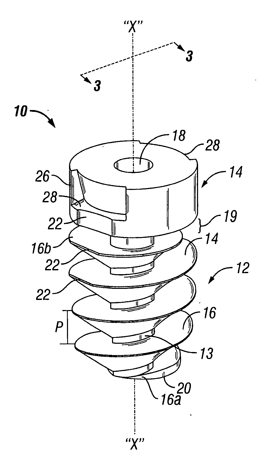
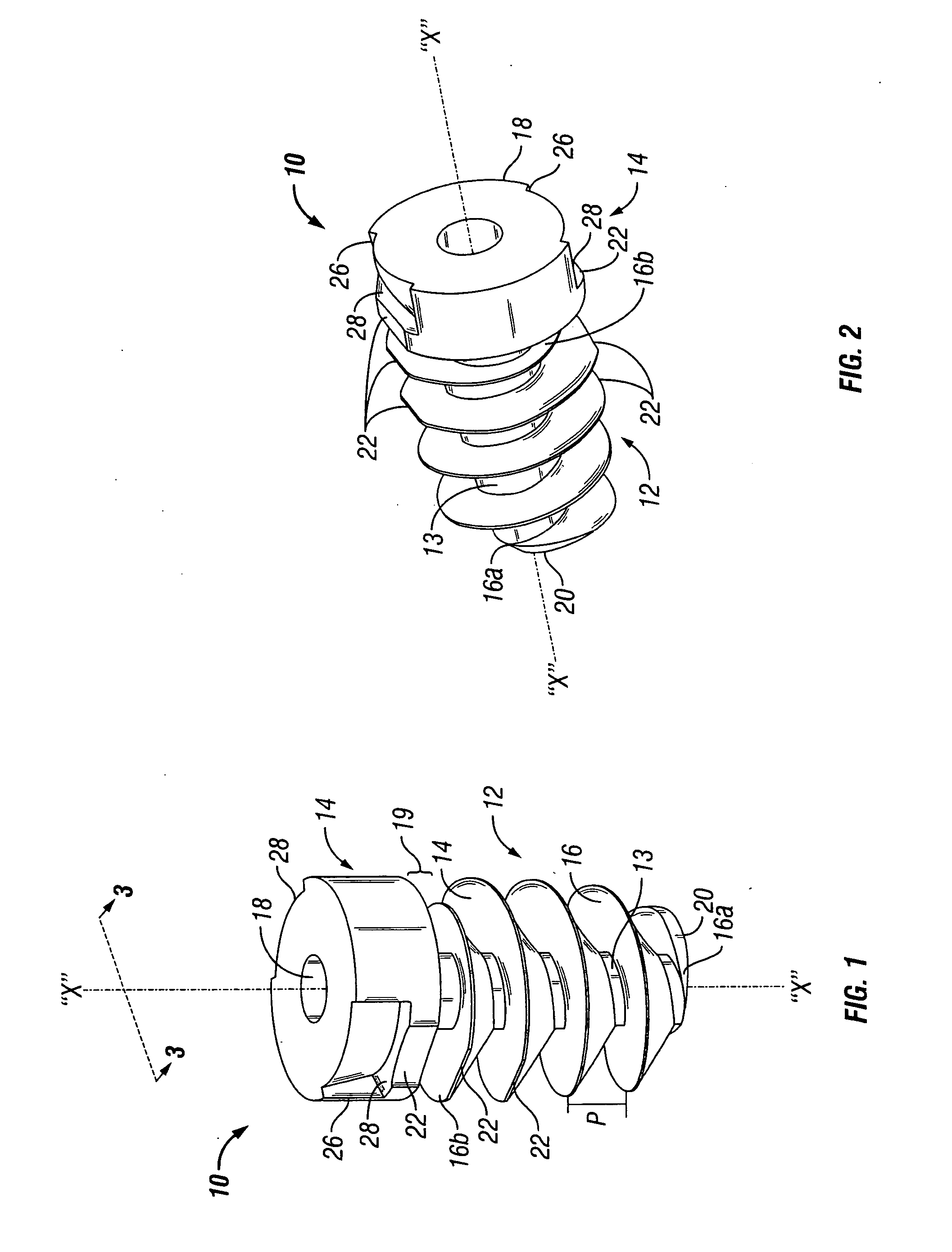
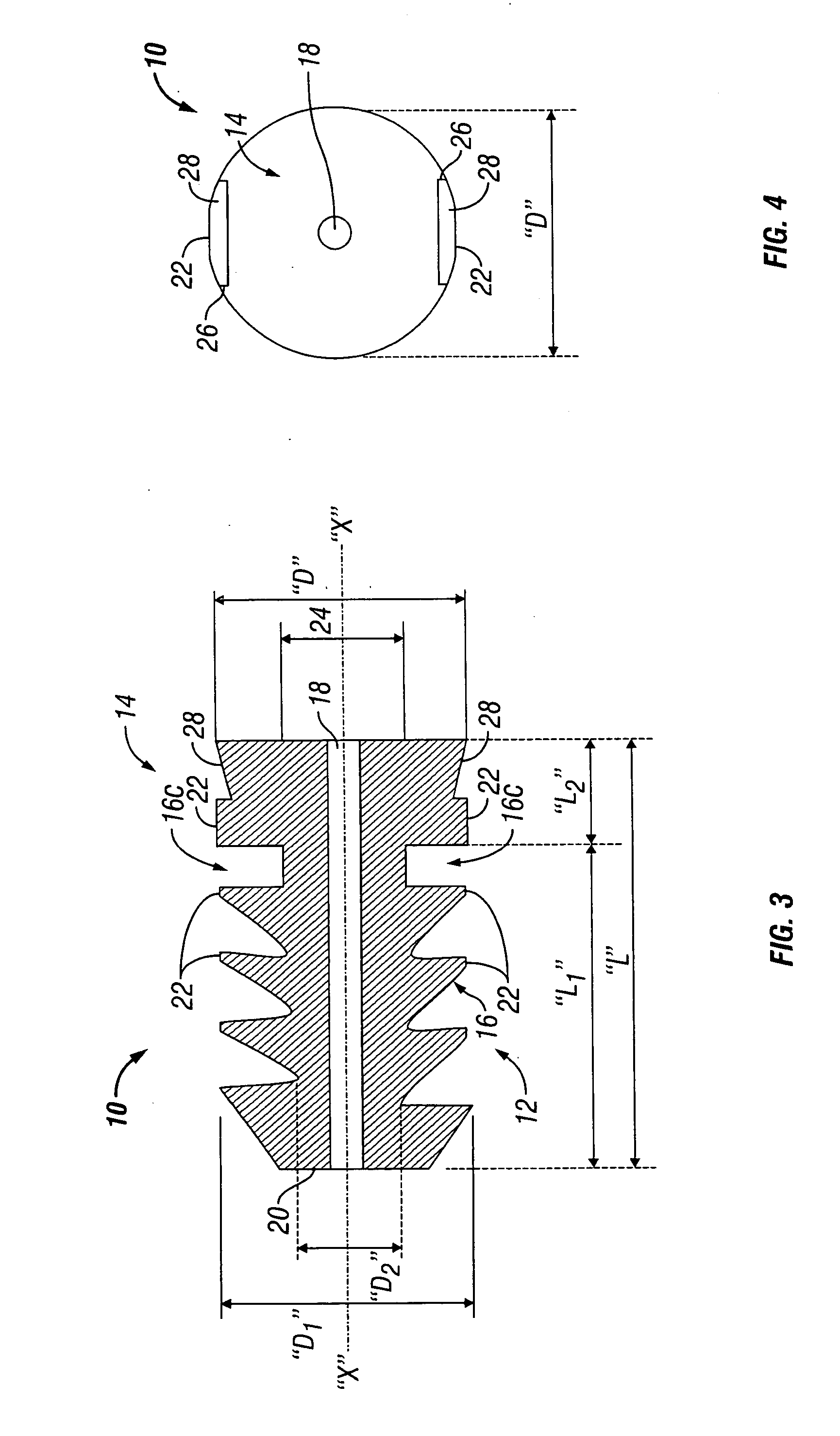
[0011] In another embodiment, the resorbable fastener is a screw fastener which includes a body portion having a helical thread, a head portion disposed at the proximal end of the body portion and a blunt end at a distal portion of the body portion. The head portion includes a driver receiving configuration on its outer diameter, said driver receiving configuration is used to transmit both linear and rotational forces in order to drive the resorbable screw fastener. The body portion of the bioresorbable fastener is threaded, with the spacing between adjacent threads being augmented to provide a wider pitch. In addition, the thread's outer diameter is enlarged creating substantially more land, giving the resorbable screw fastener greater stability and preventing dislodgement from the body tissue. The resorbable screw fastener includes a cannulated center lumen with an opening extending from the head portion through the longitudinal length of the body portion of the resorbable fastener. The head portion may also include a flat segment, which may further extend to the outside of the threads.

Problems solved by technology

Surgical fasteners are used to eliminate the need for suturing, which is often time consuming and inconvenient.
A disadvantage of permanent metal staples and / or those that remain in the body for an extended period of time is the possibility of the formation of excessive scar tissue (adhesions), which in turn can cause further patient complications and hinder future surgical procedures.
In addition, these permanent or long-term staples may be associated with increased discomfort to the patient over time as a result of the hernia repair procedure.

Method used


Image

  • Surgical fastener with predetermined resorption rate
  • Surgical fastener with predetermined resorption rate
  • Surgical fastener with predetermined resorption rate

Examples


first embodiment

[0108] In another embodiment, the fasteners of the present disclosure may have a clip structure, such as the clip depicted in FIGS. 46-48. FIG. 46 shows a clip fastener according to the present disclosure. Clip 500 has a monolithic structure including a distal anchoring rod 502 and a proximal stop bar 504 which are linked via connecting rod 506. Distal anchoring rod 502 and proximal stop bar 504 extend transversely with respect to connecting rod 506. Anchoring rod 502 and proximal stop bar 504 extend on either side of connecting rod 506 in such a way as to form an “H”.

[0109] Anchoring rod 502 extends in a first direction P of penetration and spacing-apart of an anatomical support 508, in which direction said rod is introduced. The connecting rod 506 extends in a second direction R of retention in which clip 500 is retained in the flesh, by traction from the proximal stop bar 504. Connecting rod 506 is arranged relative to anchoring rod 502 so as to have an inoperative position in wh...

second embodiment

[0112] In accordance with FIGS. 47 and 48, and according to the invention, the clip 500 has, as before, a monolithic structure, and comprises a distal anchoring rod 502 in the anatomical support, a proximal stop bar 504 relative to the prosthetic part, and a connecting rod 506 made in one piece linking the distal anchoring rod 502 and the proximal stop bar 504. As before, the connecting rod 506 is arranged relative to the distal anchoring rod 502 so as to determine at least two positions of this connecting rod 506, namely: an inoperative position in which the connecting rod 506 is arranged along a first direction R; and a stressed position in which the connecting rod 506 is folded back along a second direction P, corresponding to the direction of penetration into the anatomical support of the distal anchoring rod 502, and this against the latter.

[0113] According to the present disclosure, in the inoperative position of the connecting rod 506, the first direction R is inclined relati...


PUM

PropertyMeasurementUnit
timeaaaaaaaaaa
timeaaaaaaaaaa
timeaaaaaaaaaa

Abstract

A resorbable screw fastener and a method of firing with an applicator capable of applying a surgical fastener to tissue in order to form tissue connection to secure objects to tissue, the fastener including a body portion having a helical thread, a head portion disposed at the proximal end of the body portion. The resorbable screw fastener is 100% resorbed in vivo during a period of time ranging from about 14 days to about one year after implantation.

Description

CROSS REFERENCE TO RELATED APPLICATIONS [0001] This application is a continuation in part of, and claims the benefit of and priority to, International Application PCT / US04 / 18702 filed on Jun. 14, 2004 which, in turn, claims the benefit and priority to U.S. Provisional Patent Application Ser. No. 60 / 478,352 filed on Jun. 13, 2003, the disclosures of each of which are hereby incorporated by reference herein.BACKGROUND OF THE INVENTION [0002] 1. Technical Field [0003] The present disclosure relates generally to surgical fasteners, surgical fastener appliers and methods for connecting body tissue and, more particularly, to bioresorbable screw fasteners, screw fastener appliers, and methods of using the screw fastener applier to fire multiple resorbable screw fasteners to a target surgical site. [0004] 2. Description of Related Art [0005] Surgical fasteners are used to eliminate the need for suturing, which is often time consuming and inconvenient. Surgical fasteners accomplish in second...

Claims


Application Information

Patent Timeline
Patent Type & Authority Applications(United States)
IPC IPC(8): A61B17/00A61B17/56A61B17/86A61B17/88A61LA61L31/06A61L31/14
CPCA61B17/064A61B17/068A61B17/861A61B17/862A61B17/8635A61B17/864A61B17/866A61B17/869A61B17/8883A61B17/8891A61B2017/00004A61B2017/0648A61L31/06A61L31/148B25B13/481B25B17/00B25B23/065B25B23/101A61B17/08Y10S606/916C08L67/04A61B17/0401A61B17/8625A61B2017/0409A61B2017/0441A61F2/0063A61F2220/0016
Inventor CORRADI, RALPH ROBERTFOWLER, DAVID N.CRISCUOLO, CHRISTOPHER J.ZERGIEBEL, EARLBETTUCHI, MICHAELVIOLA, FRANK J.
Owner TYCO HEALTHCARE GRP LP
Why Eureka
Try Eureka