Dust extracting device

a technology of dust extraction device and dust, which is applied in the direction of portable percussive tools, maintenance and safety accessories, and portable power-driven tools. it can solve the problems of incomplete closing, low efficiency, and relatively easy malfunction of closure devices

Inactive Publication Date: 2005-12-08
HILTI AG
View PDF12 Cites 25 Cited by
  • Summary
  • Abstract
  • Description
  • Claims
  • Application Information

AI Technical Summary

Benefits of technology

[0005] The object of the present invention is to eliminate the aforementioned drawbacks by an extracting device hel...

Problems solved by technology

This type of closure device is relatively prone to malfunction.
In addition, it is also possible that over time the closure element is permanently deformed, whereby incomplete closing ...

Method used


Image

  • Dust extracting device
  • Dust extracting device
  • Dust extracting device

Examples


Embodiment Construction

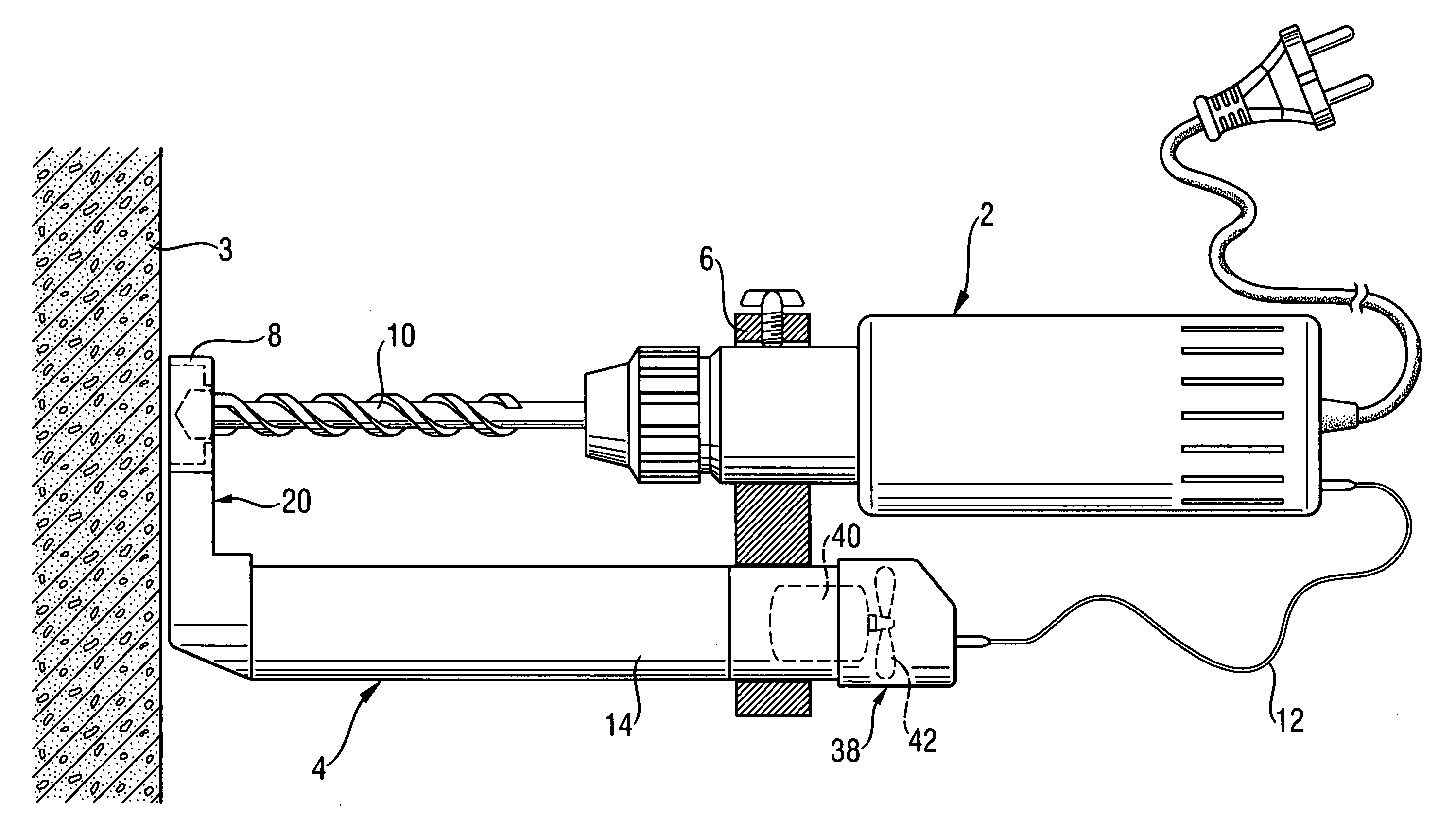
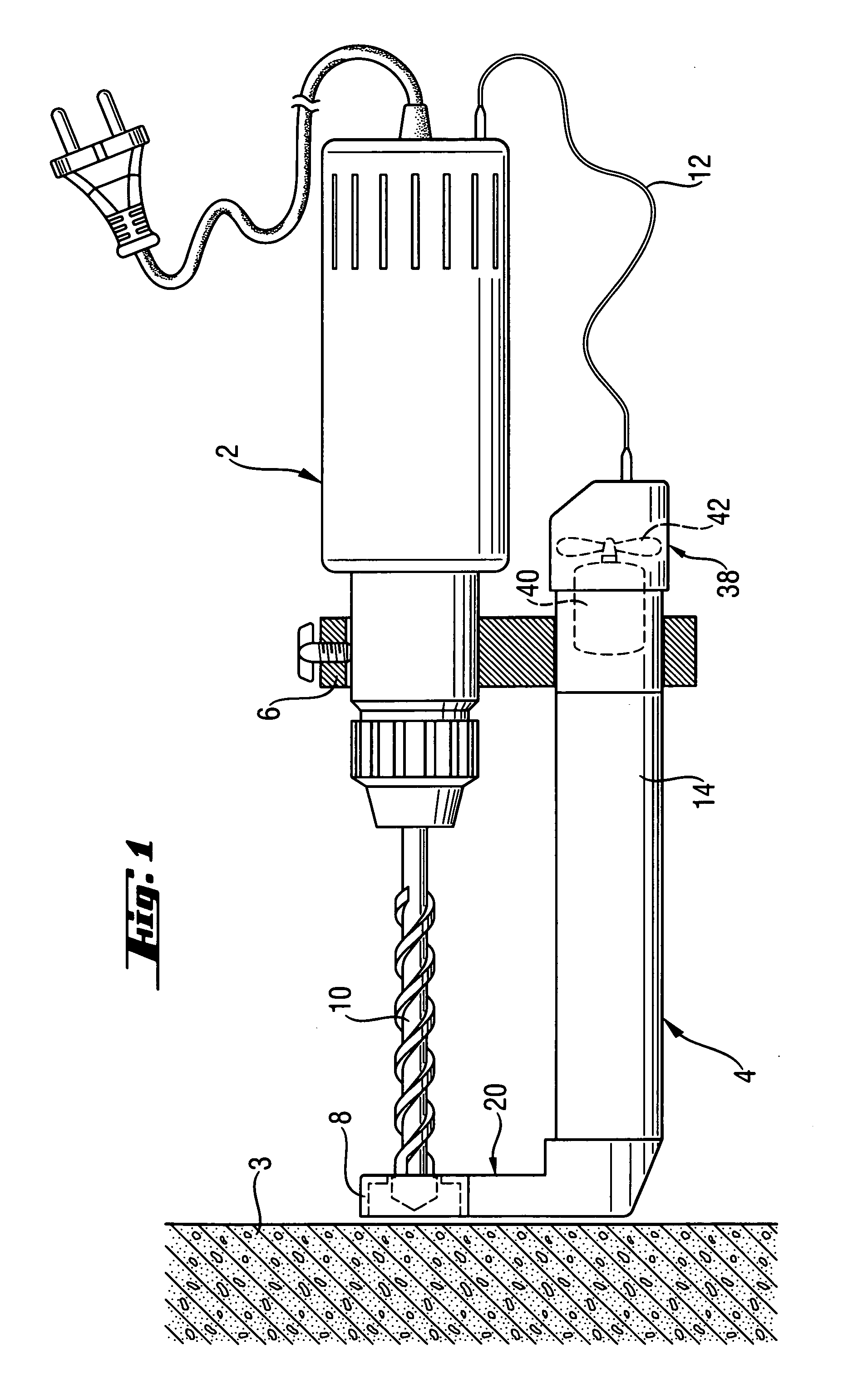
[0018]FIG. 1 shows a hand-guided electrical drilling device 2, for example in the form of a hammer drill, which is used for drilling holes in a work piece 3. To avoid soiling the surrounding area with the drill cuttings and dust produced during the drilling operation, an extracting device 4 is removably mounted on the drilling machine 2 using a carrier device 6. Alternatively, the extracting device 4 can also be integrated into the drilling machine 2.

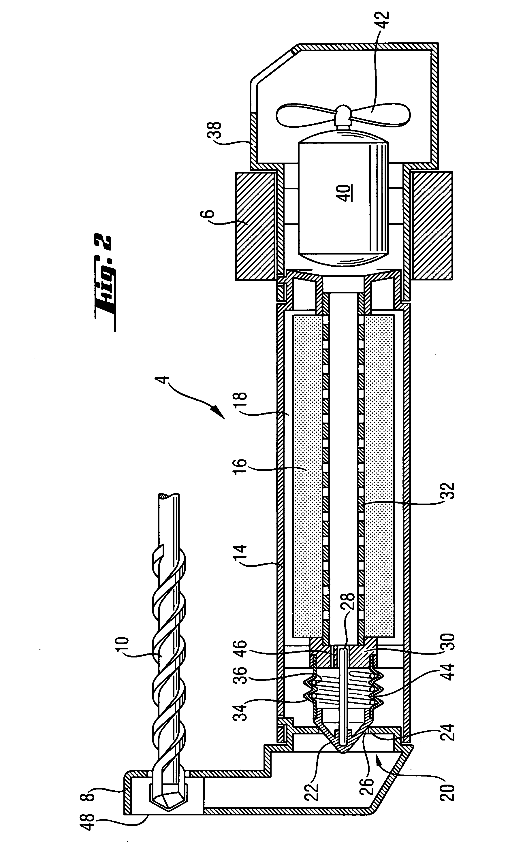
[0019] The extracting device 4 has an extracting head 8, through which a drilling tool 10 of the drilling machine 2 is passed during operation. By switching on the drilling machine 2, the extracting device 4 is simultaneously put into operation, which is supplied with power through an electrical connection 12 from the drilling machine 2. As can be seen in FIG. 2, the extracting device 4 has a receiving tube 14, in which a filter element 16 is held. Thus, between the receiving tube 14 and the filter element 16, a receiving space 18 is f...


PUM


Abstract

An extracting device (4) for removing material cut away in the operation of a motor-driven hand tool, has an extracting opening (48) and a receiving space (18) for the cut material, which communicate with one another through an extracting path, and an air current generator (42) for generating an air current (L) from the extracting opening (48) to the receiving space (18). A closure device (20) is provided between the extracting opening (48) and the receiving space (18), which at least substantially places the extracting path in a closed position and which is operated by the air current (L). The closure device (20) is arranged between the extracting opening (48) and the air current generator (42) and the closure device (20) has a closure element (22), which can be removed from a valve seat (24) by means of an underpressure created by the air current generator (42) for forming an open position of the closure device.

Description

BACKGROUND OF THE INVENTION [0001] The invention relates to an extracting device for removing material cut during operation of a motor-operated hand tool, which is attached to the hand tool for extracting such material, the device having an extracting opening and a receiving space for receiving the cut material, which is combined together over an extracting path with an air current from the extracting opening to the receiving space, wherein a closure mechanism is provided between the extracting opening and the receiving space, having a closed position at least substantially closing the extracting path and is operated by the air current. [0002] In an extracting device of this type, the closure device assures, that after the air current generator is switched off and independently of the orientation of the hand tool and the extracting device fastened to it, no cut material is released from the receiving space through the extracting opening. [0003] U.S. Pat. No. 6,047,693 discloses a mo...

Claims


Application Information

Patent Timeline
IPC IPC(8): A47L9/00B23Q11/00A47L9/10A47L9/12B23B45/00B23B47/34B25D17/18B25F5/00
CPCA47L9/102A47L9/127Y10T408/564Y10T408/50Y10T409/304088B23Q11/0046
Inventor BRITZ, RORY
Owner HILTI AG
Why Eureka
Try Eureka