Electromagnetic clutch with elastic member easily melted

a technology of elastic member and clutch, which is applied in the direction of mechanical actuated clutch, friction lining, coupling, etc., can solve the problems of difficulty in shutting off power transmission, belt damage, and cost increas

Inactive Publication Date: 2005-12-08
DENSO CORP
View PDF8 Cites 12 Cited by
  • Summary
  • Abstract
  • Description
  • Claims
  • Application Information

AI Technical Summary

Benefits of technology

[0016] With this configuration, it becomes possible to efficiently transmit heat produced at the frictional surface to the elastic member by utilizing the characteristics of the electromagnetic clutch, according to the prior art described in Patent document 1, that the performance thereof for damping vibration is excellent and the performance of absorbing torque variations which reduces magnitude of torque variations is excellent and further by forming a structure in which the outer plate and the armature are integrally coupled to each other, thereby giving no gap therebetween. Due to this, as it becomes easy to melt the elastic member and shut off power transmission, a much safer electromagnetic clutch can be provided.
[0022] According to the present aspect, as the transmission of the heat produced at the frictional surface to the elastic member becomes more efficient, it becomes easy to more quickly melt the elastic member and shut off power transmission.
[0024] According to the present aspect, the outer plate has a simple shape and it is easy to transmit heat from the armature to the elastic member via the outer plate.
[0026] According to the present aspect, there is the possibility that the manufacture of the outer plate and the armature becomes easier while it is easy to melt the elastic member and shut off power transmission.

Problems solved by technology

However, when the compressor locks or if trouble occurs in the compressor without driver's knowledge, the electromagnetic clutch slips and produces heat and there may arise the possibility that another trouble, such as the breakage of a belt, occurs.
However, a temperature fuse poses a problem that it takes time to shut off power transmission and a lock sensor poses a problem that the cost is raised.
In this structure, when the compressor locks, the heat produced at the frictional surface between the rotor 31 and the armature 14 is unlikely to be transmitted to the cylindrical rubber 11 and it takes time for the cylindrical rubber 11 to melt and shut off power and, therefore, there is the possibility that the belt is damaged.
In this art, as there is a gap between an armature and an outer plate, heat is unlikely to be transmitted and, therefore, it is difficult to shut off power transmission.
However, there arises a problem that the damping effect is slight and the performance of absorbing torque variations is poor although the member is readily melted to shut off power transmission.

Method used


Image

  • Electromagnetic clutch with elastic member easily melted
  • Electromagnetic clutch with elastic member easily melted
  • Electromagnetic clutch with elastic member easily melted

Examples


first embodiment

[0057] The following effect can be expected from the electromagnetic clutch 1 in the present invention.

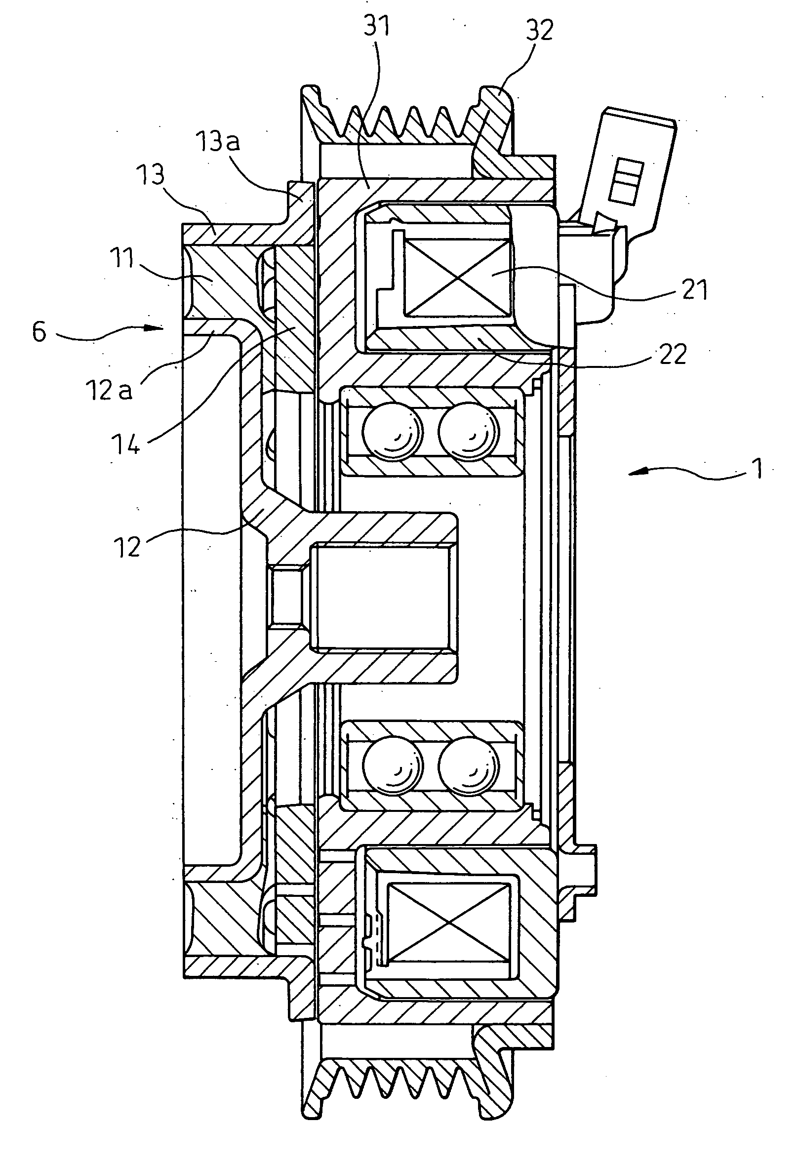
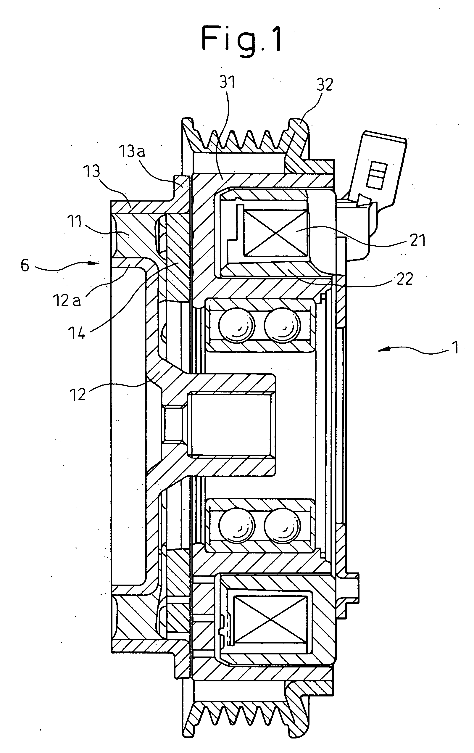
[0058] The electromagnetic clutch 1 according to the prior art described in Patent document 1 has a great damping effect and excellent performance of absorbing torque variations. Therefore, by integrally forming the outer plate and the armature into one piece with no gap in between in this structure, the transmission of the heat produced at the frictional surface to the elastic member becomes more efficiently. As a result, it becomes easy to melt the elastic member to stop power transmission.

[0059] In addition to the effect of the first embodiment described above, the following effect can be expected from the electromagnetic clutch in the second embodiment of the present invention.

[0060] In the first embodiment, the electromagnetic coil of the electromagnetic clutch has six poles but the present invention can be applied to the case of the four-pole electromagnetic coil.

[0061] In...

third embodiment

[0064] Another embodiment different from the third embodiment is disclosed, in which the structure has no armature outer ring and as for heat transmission, and it is easy to transmit heat from the armature to the elastic member.

[0065] In addition to the effect of the first embodiment described above, the following effect can be expected from the electromagnetic clutch in the fifth embodiment of the present invention.

[0066] It is possible to increase the contact area between the outer plate and the armature and, thereby, heat is readily transmitted to the elastic member.

[0067] In addition to the effect of the first embodiment described above, the following effect can be expected from the electromagnetic clutch in the sixth embodiment of the present invention.

[0068] Compared to the third embodiment described above, heat is more readily transmitted from the armature to the elastic member via the outer plate and, therefore, it is possible to melt the elastic member more quickly.

[006...


PUM


Abstract

The electromagnetic clutch comprises a rotor connected to a drive source, an inner hub connected to a device that follows, an outer plate provided on the outside of the inner hub so as to enclose it, an armature coupled to the outer plate and opposing the rotor, an elastic member provided between the inner hub and the outer plate and adhered thereto, and an electromagnetic coil for, when magnetized, attracting the armature together with the outer plate to make them come into contact with the rotor, and when demagnetized, separating the outer plate and the armature from the rotor. Because of the configuration in which the armature and the outer plate are coupled in a heat-transmissible manner, a part of elastic member is formed so that heat is transmitted from at least a part of the armature to the part of the elastic member as if they are one piece.

Description

BACKGROUND OF THE INVENTION [0001] 1. Field of the Invention [0002] The present invention relates to an electromagnetic clutch and, more particularly, to an electromagnetic clutch used for connecting and disconnecting a compressor of an air conditioner in a vehicle. [0003] 2. Description of the Related Art [0004] In a vehicle, an engine, which is a drive source, is used not only as a drive source for moving a vehicle but also as a drive source for various devices. There are many vehicles in which the compressor of an air conditioner for a vehicle is driven by an engine via a belt etc. In this case, the load applied to the engine can be reduced and fuel consumption can be improved by separating the compressor from the engine when it is not necessary to drive the air conditioner for a vehicle. It is also preferable, from the standpoint of life of the compressor to stop the compressor when not required. Because of such a need, an electromagnetic clutch is arranged between an engine and...

Claims


Application Information

Patent Timeline
Patent Type & Authority Applications(United States)
IPC IPC(8): F16D27/112F16D19/00F16D27/10F16D27/14
CPCF16D27/112F16D2027/008F16D27/14F16D27/00F16D27/10
Inventor OHTSUKA, KAZUHIKOTABUCHI, YASUOHAYASHI, TOSHIHIRO
Owner DENSO CORP
Why Eureka
Try Eureka