Controller for a wire electrical discharge machine

Active Publication Date: 2005-12-08
FANUC LTD
View PDF5 Cites 22 Cited by
  • Summary
  • Abstract
  • Description
  • Claims
  • Application Information

AI Technical Summary

Benefits of technology

[0051] According to the present invention, stable machining by a wire electrical discharge machine can be carried out a

Problems solved by technology

It has been confirmed that when the nozzle is in tight contact with a machining start hole and the hole diameter is smaller than the nozzle diameter, short circuits occur repeatedly near the hole and machining may become unstable.
Possible causes of this problem are that if the nozzle covers the hole completely, it prevents proper discharging of the machining fluid ejected from the nozzle, so that metal particles and bubbles are not discharged away properly, and that turbulence of the machining fluid further amplifies wire vibration.
This problem continues until the nozzle moves off the start hole so that the machining fluid can be adequately discharged.
Furthermore, machining is always performed, under weakened conditions regardless of whether control dependent on the machining state is necessary, also lowering the machining efficiency.
Machining still always starts under weakened conditions regardless of whether control is necessary, and the above problem remains.
A possible problem in patent document 4 is that control is not activated until a voltage change is detected during machining, without regard to the machining start point, as a result, the groove width may change during the machining process.
Furthermore, because control is not activated until a voltage change is detected, machining is performed under intensive conditions in the normal state until the voltage change is detected.
Considering the problems that occur at the machining start point and at the ends of workpieces, there is a risk that the wire may break immediately after a discharge, that is, before an abnormal discharge is detected due to a voltage change.
There is also a problem that preparation of conditions for stable machining involves extra work.
Although enabling and disabling of this function is switched by a program command or on-screen setting, this still requires extra work by an operator.
It is also difficult to correctly determine whether such control is

Method used


Image

  • Controller for a wire electrical discharge machine
  • Controller for a wire electrical discharge machine
  • Controller for a wire electrical discharge machine

Examples


first embodiment

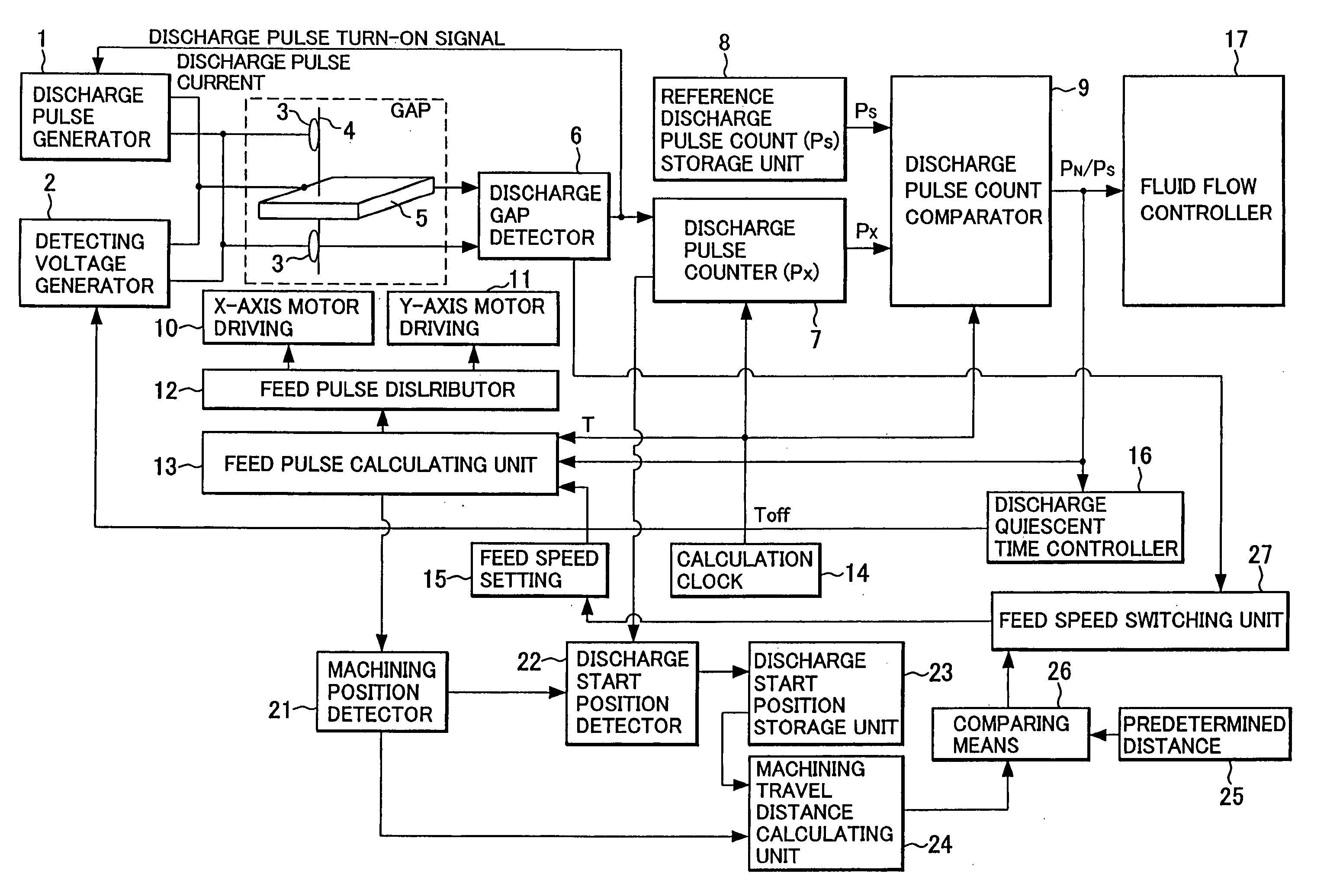
[0112]FIG. 3 is a block diagram illustrating main elements of the controller for a wire electrical discharge machine according to the present invention.

[0113] Reference numeral 1 in FIG. 3 indicates a discharge pulse generator comprising a circuit having transistors and other active elements for generating discharge pulse current, a capacitor charging / discharging circuit, a direct current power supply, etc. One of the outputs from the discharge pulse generator 1 is connected to the workpiece 5 and the other is connected to contact brushes 3 disposed above and below the workpiece 5, supplying pulsed discharge current to a gap between the running wire electrode 4 and workpiece 5.

[0114] Reference numeral 2 indicates a detecting voltage generator comprising a direct current power supply, a circuit having resistors, capacitors, and active elements such as transistors etc. for generating a voltage for detecting the state of the gap, and other components. One of the outputs from the detec...

second embodiment

[0163]FIG. 8 is a block diagram illustrating main elements of the controller for a wire electrical discharge machine according to the present invention. Only the differences from the first embodiment shown in FIG. 3 will be described below.

[0164] In the second embodiment, instead of counting and storing the number of discharge pulses, the integrated value of discharge pulse current is obtained from a current detecting circuit 18 and a discharge pulse current integrated value calculation and storage unit 37. Further, instead of the reference discharge pulse count storage unit, a reference discharge pulse current integrated value storage unit 38 is provided. Then, ratios used for controlling feed pulses, discharge quiescent time and fluid flow are calculated and outputted by a discharge pulse current integrated value comparator 39.

[0165] More specifically, a reference integrated value of the discharge pulse current is set, instead of the reference number Ps of discharge pulses per un...


PUM

PropertyMeasurementUnit
Timeaaaaaaaaaa
Ratioaaaaaaaaaa
Speedaaaaaaaaaa

Abstract

Set feed speed is lowered when a short circuit is detected in a range within which machining is unstable, the range starting from the point at which discharge is detected after machining starts from a machining start point, thus control is carried our according to a machining rate, thereby preventing successive occurrence of short circuits. When machining proceeds beyond the unstable range, the lowered feed speed is returned to the normal feed speed.

Description

BACKGROUND OF THE INVENTION [0001] 1. Field of the Invention [0002] The present invention relates to control of wire electrical discharge machines and, more particularly, to a controller and a control method by which increased machining efficiency is achieved. [0003] 2. Description of the Prior Art [0004] In wire electrical discharge machining, corners and other parts of a workpiece at which a wire tends to break require additional corner control and other processing such as, for example, lowering feed speed and machining current in advance. To cope with this problem, a controller for a wire electrical discharge machine has been proposed that detects an electrical discharge machining rate and controls machining speed, machining energy and flow of machining fluid accordingly to the change in the electrical discharge machining rate to prevent wire breakage and increase the machining accuracy at corners (see patent document 1 below). [0005] The above-described controller achieves stabl...

Claims


Application Information

Patent Timeline
IPC IPC(8): B23H7/04B23H7/06B23H7/14B23H7/20
CPCB23H7/04B23H7/20B23H7/065
Inventor ARAKAWA, YASUOOGATA, TOSHIYUKIHIRAGA, KAORU
Owner FANUC LTD
Why Eureka
Try Eureka