

Electric discharge machine
- Summary
- Abstract
- Description
- Claims
- Application Information
AI Technical Summary
Benefits of technology
Problems solved by technology
Method used
Image

Examples
first embodiment
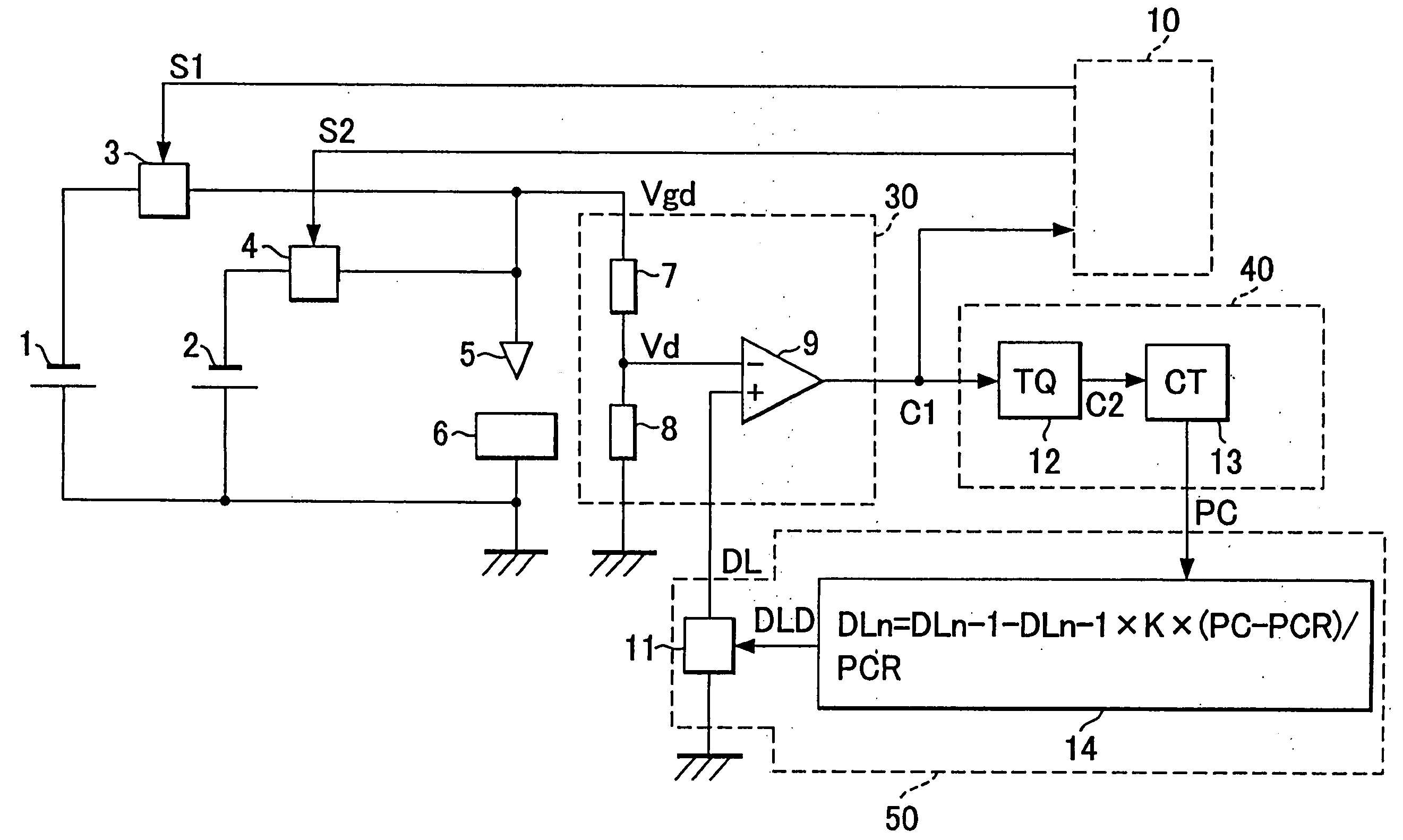
[0082]FIG. 5 shows an exemplary structure of the The dividing resistors 7 and 8 and the comparator 9 shown in FIG. 5 constitute the detection circuit 30 shown in FIG. 1. In the actual circuit, the detected voltage Vgd is divided by the dividing resistors 7 and 8. The detection level DL is set according to the value to which the detected voltage is divided by the dividing resistors 7 and 8 when power is supplied from the main power supply. The comparator 9 compares the voltage Vd, obtained by dividing the detected voltage Vgd by the dividing resistors 7 and 8 with the detection level DL, and outputs signal C1.
[0083] The monostable multivibrator 12 and counter 13 shown in FIG. 5, which constitute the machining state detecting means 40 shown in FIG. 1, count the number of C1 outputs from the comparator 9. This count represents the number of times PC the main power supply 2 supplies power.
[0084] The arithmetic circuit 14 and D / A converter 11 shown in FIG. 5 constitute the detection le...
second embodiment
[0103]FIG. 8 shows an exemplary structure of the The dividing resistors 7 and 8 and the comparator 9 shown in FIG. 8 constitute the detection circuit 30 shown in FIG. 1. The detected voltage Vgd is divided by the dividing resistors 7 and 8. The detection level DL is set to a value obtained by dividing the detected voltage by the dividing resistors 7 and 8 when power is supplied from the main power supply. The comparator 9 compares the voltage Vd, obtained by dividing the detected voltage Vgd by the dividing resistors 7 and 8 with the detection level DL, and outputs signal C1.
[0104] The counter 15 and clock circuit 16 shown in FIG. 8, which constitute the machining state detecting means 40 shown in FIG. 1, measure the time interval TD from when voltage is applied by the sub-power supply until power is supplied from the main power supply, according to output C1 from the comparator 9.
[0105] The arithmetic circuit 17 and D / A converter 11 shown in FIG. 8 constitute the detection level ...
PUM
| Property | Measurement | Unit |
|---|---|---|
| Electric potential / voltage | aaaaa | aaaaa |
Abstract
Description
Claims
Application Information