
Electromagnetic valve assembly for controlling airbag

a technology of electromagnetic field and airbag, which is applied in the direction of valve housing, pedestrian/occupant safety arrangement, vehicular safety arrangement, etc., can solve the problems of increased production cost, increased chance of malfunction, and large storage space occupation, and achieves the effect of strengthening braking time and strength

Inactive Publication Date: 2005-12-08
MANY A ENTERPRISE
View PDF11 Cites 6 Cited by
  • Summary
  • Abstract
  • Description
  • Claims
  • Application Information

AI Technical Summary

Benefits of technology

[0009] 1. automobile airbags having a greatest advantage of using free and clean air instead of hazardous chemical gases: environmental concerns are eliminated and can be repeated used by common users but not professional staff, thereby economizing time and money required;
[0010] 2. operations and controls of air pads and airbags for assisting shock absorbing of automobiles: systems can be inflated in order to lift shock absorbers of automobiles when driving on lumpy grounds, so as to prevent direct impacts of automobile chassis with the grounds; in addition, heights of automobile chassis can be dropped through deflation when automobiles are parked to provide anti-theft effects;
[0011] 3. loop controls of air-pressurized braking systems of large automobiles: the invention is capable of reinforcing braking time and strength.

Problems solved by technology

Thus, not only production costs are multiplied, but large storage spaces are also occupied.
In addition, the more apparatuses there are, the higher the chances of malfunctions.
It remains a doubtful question that whether all the multiple electromagnetic valves, at times of car accidents, are capable of simultaneous operations for reliably attending to users' safety.

Method used


Image

  • Electromagnetic valve assembly for controlling airbag
  • Electromagnetic valve assembly for controlling airbag
  • Electromagnetic valve assembly for controlling airbag

Examples


Embodiment Construction

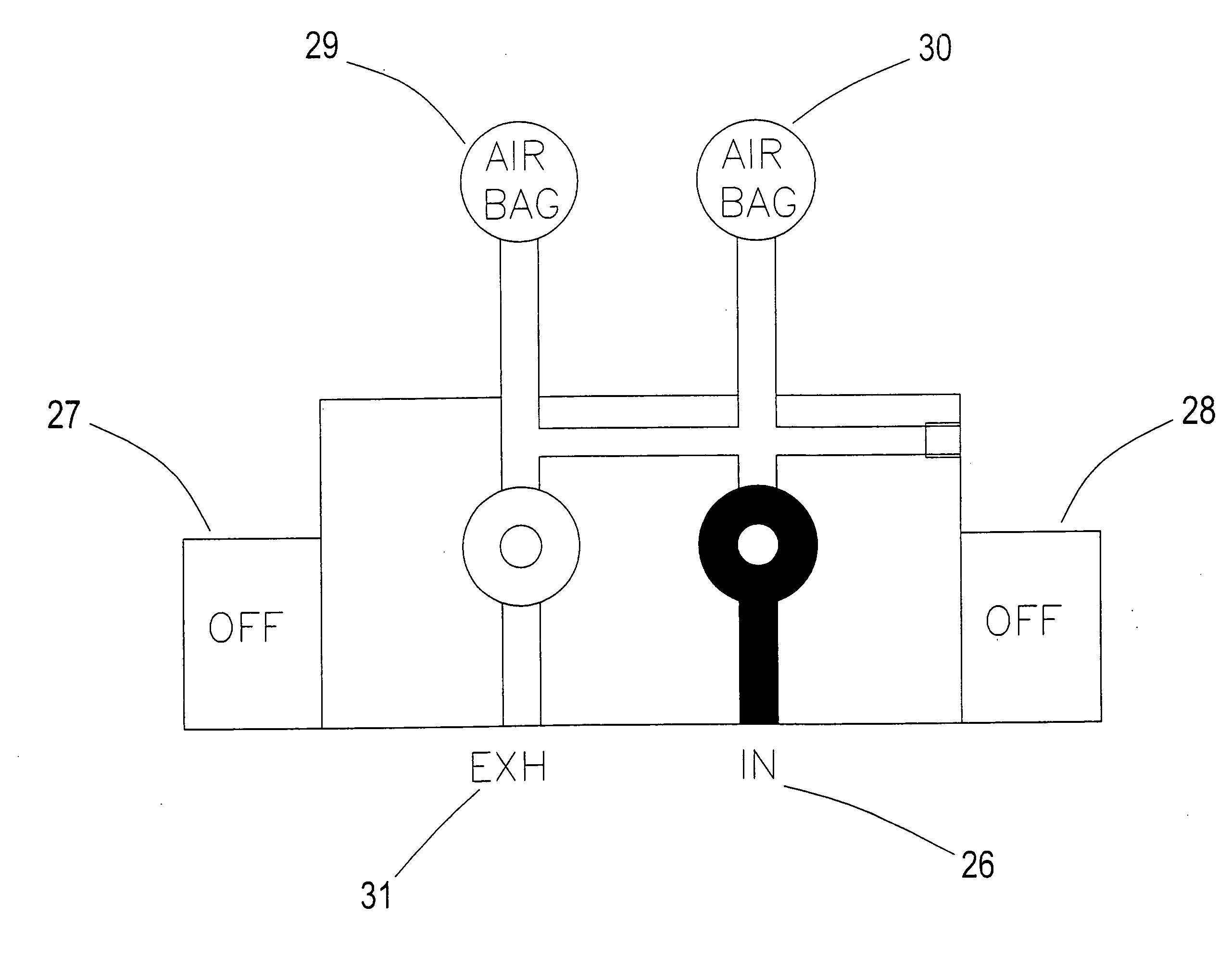
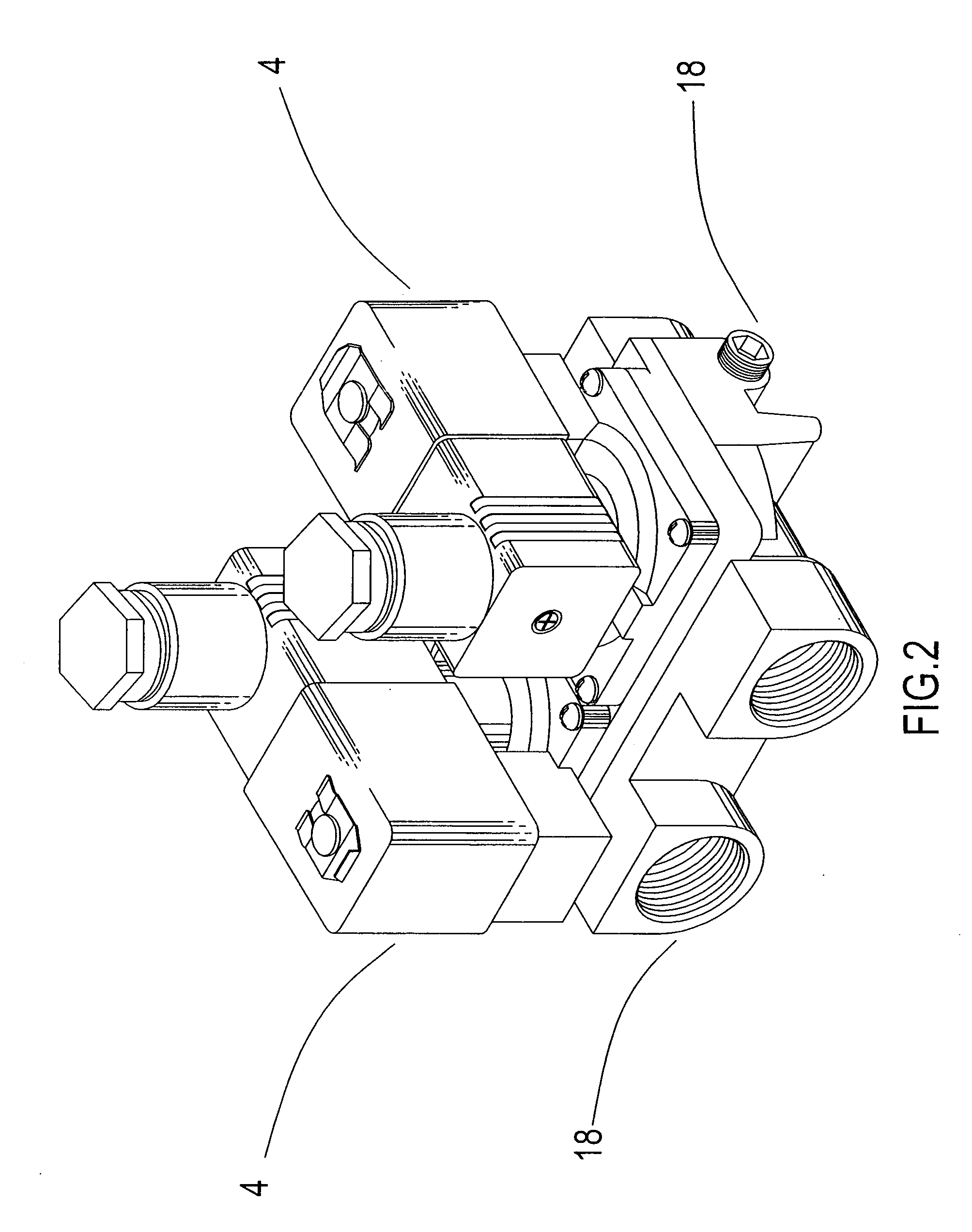
[0019] Referring to FIGS. 2 and 3, the invention comprises a main valve assembly 18 and a switch box 4.

[0020] An assembled valve is mounted with a film 16 further having a ring-shape loop 15. A side of a valve cover is connected with an electromagnetic tube 9 accommodated with a spring 11 and an electromagnet 11. A rhombus flanged 5 is utilized for pressing against a washer 7 and a ring-shaped loop 5, and are altogether fastened at a side of a valve cover using a screw 6. The electromagnetic tube 9 is placed on a coil 3, levelly covered with a washer 2 and fastened with pressed anti-sliding plate 1. The outlet at the side of the valve cover is accommodated with a ring-shaped 17 to keep being airtight with the main valve body, and is closed joined with the main valve body using a screw 12. The main valve assembly 18 is disposed with a stopper 19 at a side thereof, and a screw fastening opening 25 at a lower portion thereof for placing an L-shaped plate 20 as desired, wherein the L-s...


PUM


Abstract

An electromagnetic valve assembly for controlling airbags, includes a single valve assembly joined by main valve bodies of two electromagnetic valves each having respective electromagnetic control coils. A ventilation opening of the joined single valve assembly is placed with a film further mounted with a ring-shaped loop; an upper cover of the valve is connected with an electromagnetic tube accommodated with a spring and an electromagnetic; a rhombus flange is utilized to press against a washer and the ring-shaped loop. The electromagnetic is placed with a coil thereon and a planar washer; a ventilation opening at a side of the valve cover is placed with a ring-shaped loop to keep being airtight with the main valve body by using a screw; and the main valve is provided with a stopper at a side thereof, and an L-shaped plate being capable of adjusting installed positions.

Description

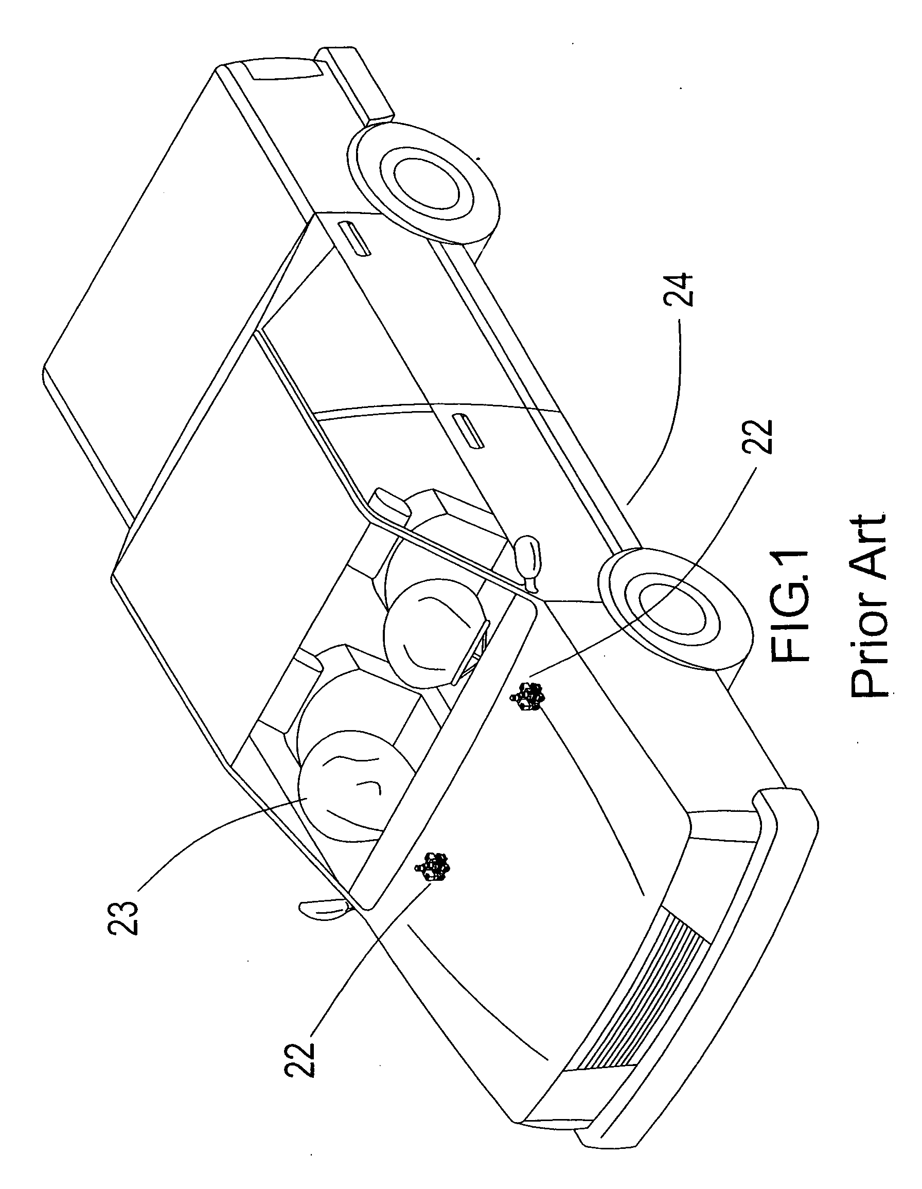
BACKGROUND OF THE INVENTION [0001] (a) Field of the Invention [0002] The invention relates to an electromagnetic valve assembly for controlling airbags, and more particularly, to an electromagnetic valve assembly for controlling airbags of an automobile. The electromagnetic valve assembly according to the present invention simplifies four independent main electromagnetic valves used for controlling inflation and deflation of two airbags of prior inventions, into one main electromagnetic valve assembly capable of simultaneous inflation and deflation, thereby significantly reducing production costs and storage spaces. [0003] (b) Description of the Prior Art [0004] Referring to FIG. 1, current automobile airbags 23 are generally chemical-gas-sensed air bags, which can be replaced by compresses gases when a valve assembly according to the invention is implemented. According to the prior invention, deflation of airbags at two sides of a driver's seat and a front passenger's seat are init...

Claims


Application Information

Patent Timeline
Patent Type & Authority Applications(United States)
IPC IPC(8): B60R21/017B60R21/16B60R21/18B60R21/33F16K11/24F16K27/00F16K31/00
CPCB60R21/017F16K27/003F16K11/24B60R21/33Y10T137/3584
Inventor KUNG, PI-FU
Owner MANY A ENTERPRISE
Learn More