Electric brake position and force sensing and control

a technology of force sensing and control, applied in the direction of braking systems, braking components, transportation and packaging, etc., can solve the problems of system prone to brake fade and/or lack of precise force application, loss of anti-skid efficiency, and increase in the running clearance of the actuator ram

Inactive Publication Date: 2005-12-08
THE BF GOODRICH CO
View PDF18 Cites 83 Cited by
  • Summary
  • Abstract
  • Description
  • Claims
  • Application Information

AI Technical Summary

Benefits of technology

[0008] According to one aspect of the invention, an electromechanical brake system is provided. The brake system includes an electromechanical brake actuator including an actuator ram for exerting a brake force on a brake stack of a wheel to be braked in response to a control signal. In addition, the brake system includes a force sensor for sensing the brake force exerted on the brake stack by the actuator ram and outputting a force feedback signal based thereon; and a position sensor for sensing a position of the actuator ram and outputting a position feedback signal based thereon. Moreover, the brake system includes a controller for providing the control signal to the elec...

Problems solved by technology

As the brake disks within the stack wear, the running clearance of the actuator rams correspondingly increases.
However, controlling the running clearance and brake force using position control was disadvantageous in that the system was susce...

Method used


Image

  • Electric brake position and force sensing and control
  • Electric brake position and force sensing and control
  • Electric brake position and force sensing and control

Examples


Embodiment Construction

[0016] The present invention will now be described with reference to the drawings, wherein like reference labels are used to refer to like elements throughout.

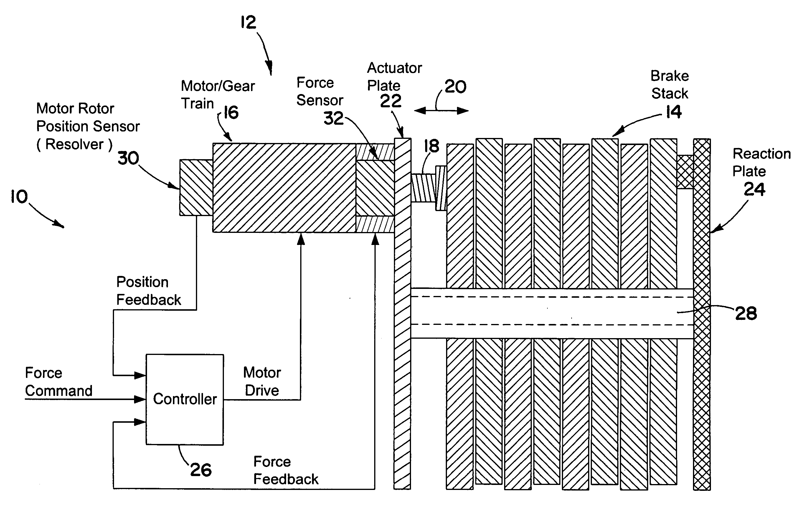
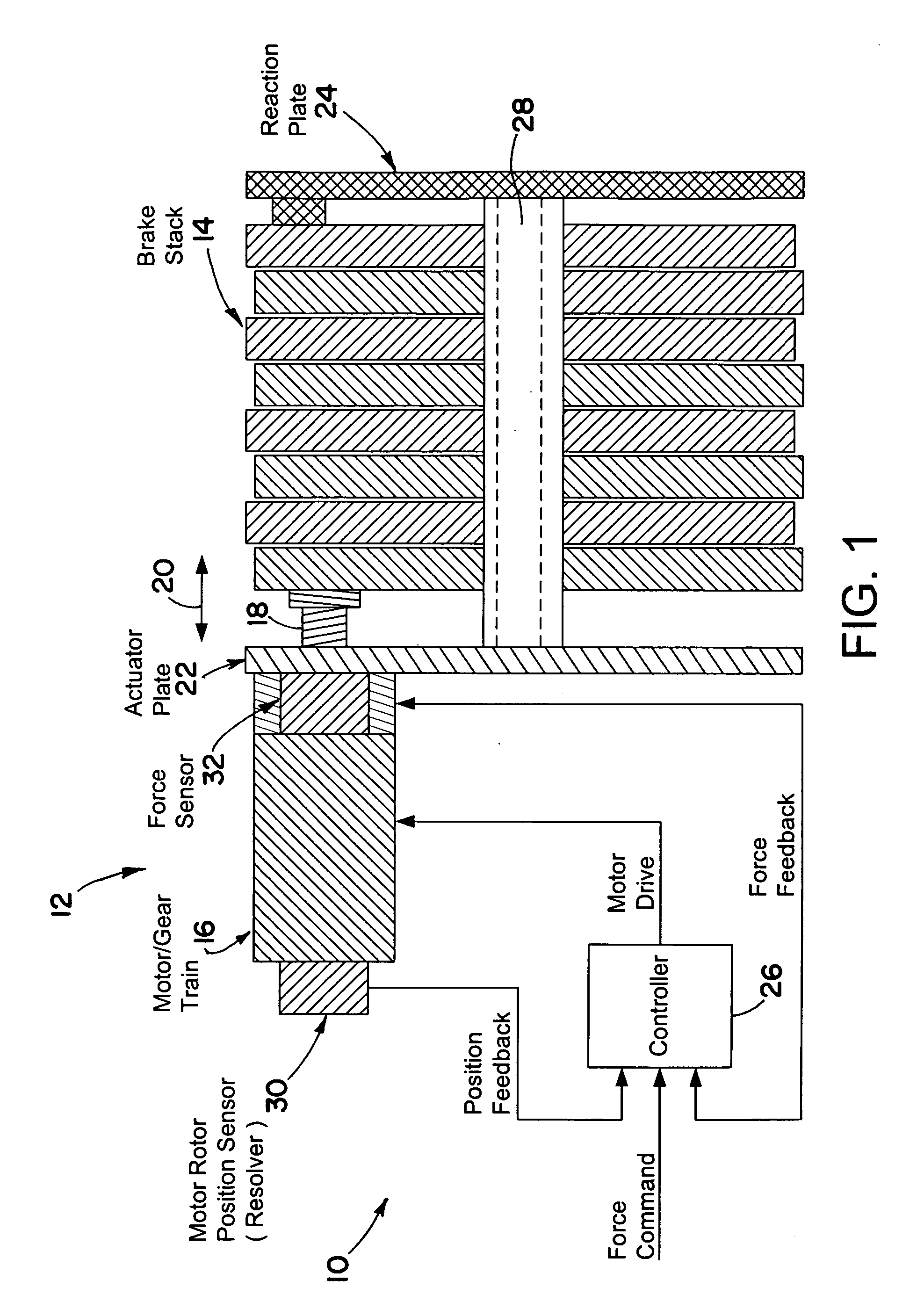
[0017] Referring initially to FIG. 1, an electric brake system 10 is illustrated in accordance with the present invention. As will be described in more detail below, the brake system 10 utilizes a force sensor that, in conjunction with a position sensor, is used to control the applied brake force and running clearance. By combining the use of both force control and a position control, the brake system 10 is less susceptible to brake fade or imprecise brake force application while still providing satisfactory running clearance adjustment.

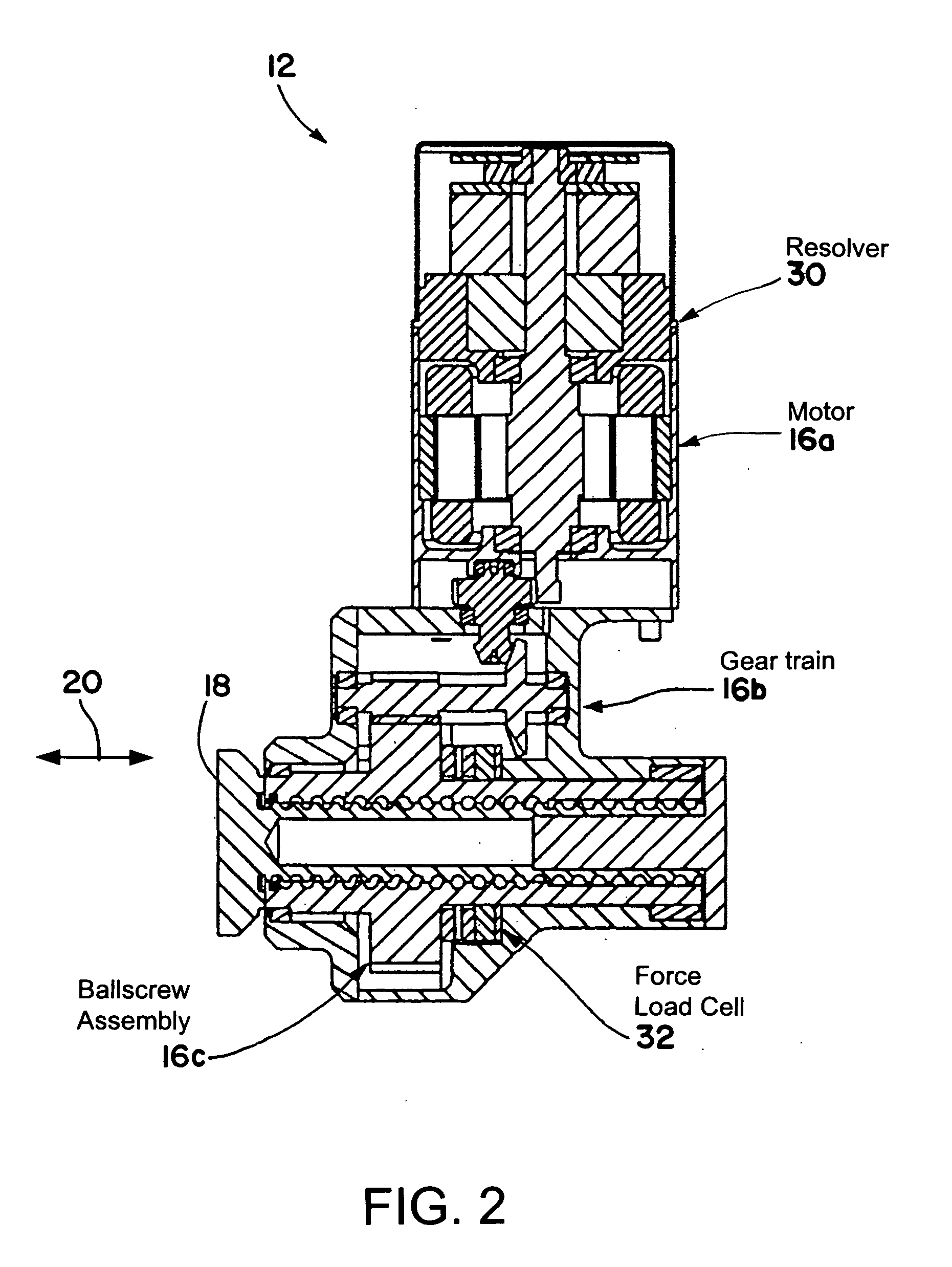
[0018] The brake system 10 includes an electromechanical actuator 12 for exerting a controlled brake force on a multiple disk brake stack 14. In the exemplary embodiment, the brake stack 14 is associated with the wheel of an aircraft (not shown) to provide braking in response to pilot command...


PUM


Abstract

A brake system including an electromechanical brake actuator having an actuator ram for exerting a brake force on a brake stack of a wheel to be braked in response to a control signal. In addition, the brake system includes a force sensor for sensing the brake force exerted on the brake stack by the actuator ram and outputting a force feedback signal based thereon; and a position sensor for sensing a position of the actuator ram and outputting a position feedback signal based thereon. Moreover, the brake system includes a controller for providing the control signal to the electromechanical brake actuator based on the force feedback signal and the position feedback signal.

Description

CROSS-REFERENCE TO RELATED APPLICATION [0001] This application claims priority under 35 USC §119 to U.S. Provisional Application No. 60 / 577,225, filed Jun. 4, 2004, the entire disclosure of which is incorporated herein by reference.TECHNICAL FIELD [0002] The invention herein described relates generally to brake control systems, more particularly to electronic braking systems, and still more particularly to aircraft braking systems. BACKGROUND OF THE INVENTION [0003] Electric brake systems are known in the prior art. In such systems, electric motor-driven actuators are designed to drive corresponding actuator rams. Typically, the actuator rams extend to compress a brake disk stack against a back plate. [0004] As the brake disks within the stack wear, the running clearance of the actuator rams correspondingly increases. To maintain an acceptable running clearance, means must be provided for adjusting the running clearance. U.S. Pat. No. 6,003,640, the entire disclosure of which is inc...

Claims


Application Information

Patent Timeline
IPC IPC(8): B60T8/00F16D65/18B60T8/17B60T13/66B60T13/74F16D65/14
CPCF16D2125/48F16D2125/50F16D2125/52B60T8/00B60T8/1703F16D2125/40F16D65/18F16D2066/003F16D2066/005F16D2121/24B60T13/741
Inventor RALEA, MIHAI
Owner THE BF GOODRICH CO
Why Eureka
Try Eureka