Method and device for reducing the signal images at the output of a digital/analogue converter
- Summary
- Abstract
- Description
- Claims
- Application Information
AI Technical Summary
Benefits of technology
Problems solved by technology
Method used
Image
Examples
Embodiment Construction
[0035] One or more implementations of the present invention will now be described with reference to the attached drawings, wherein like reference numerals are used to refer to like elements throughout, and wherein the illustrated structures are not necessarily drawn to scale.
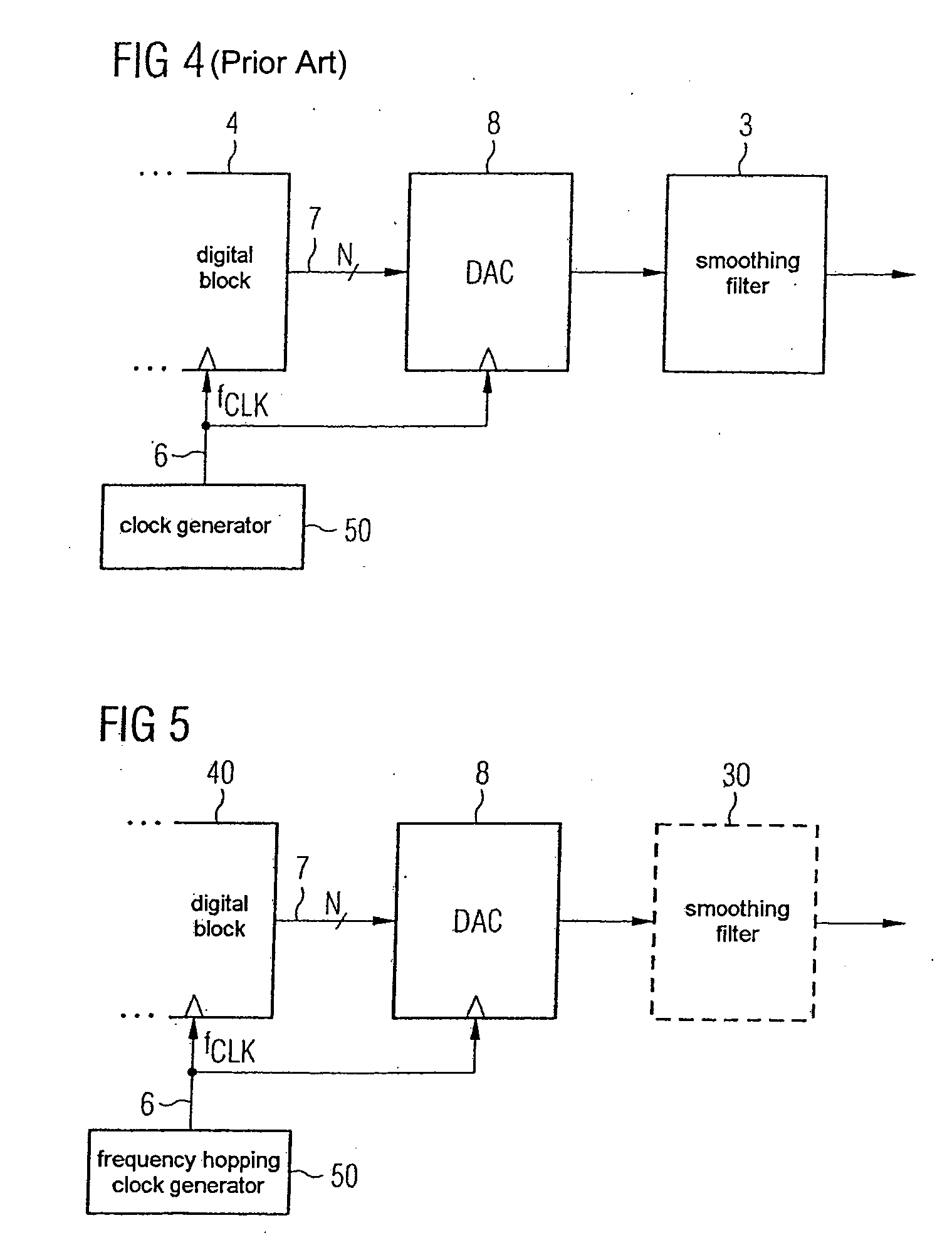
[0036] According to FIG. 4, a digital block 4 is driven by a clock generator 5 which emits a clock signal 6 with a fixed clock frequency fCLK. The digital block 4 delivers digital data words (word width N) via a data connection 7 to a digital / analogue converter 8. The data rate is fCLK, i.e. it corresponds to the clock frequency of the clock signal.
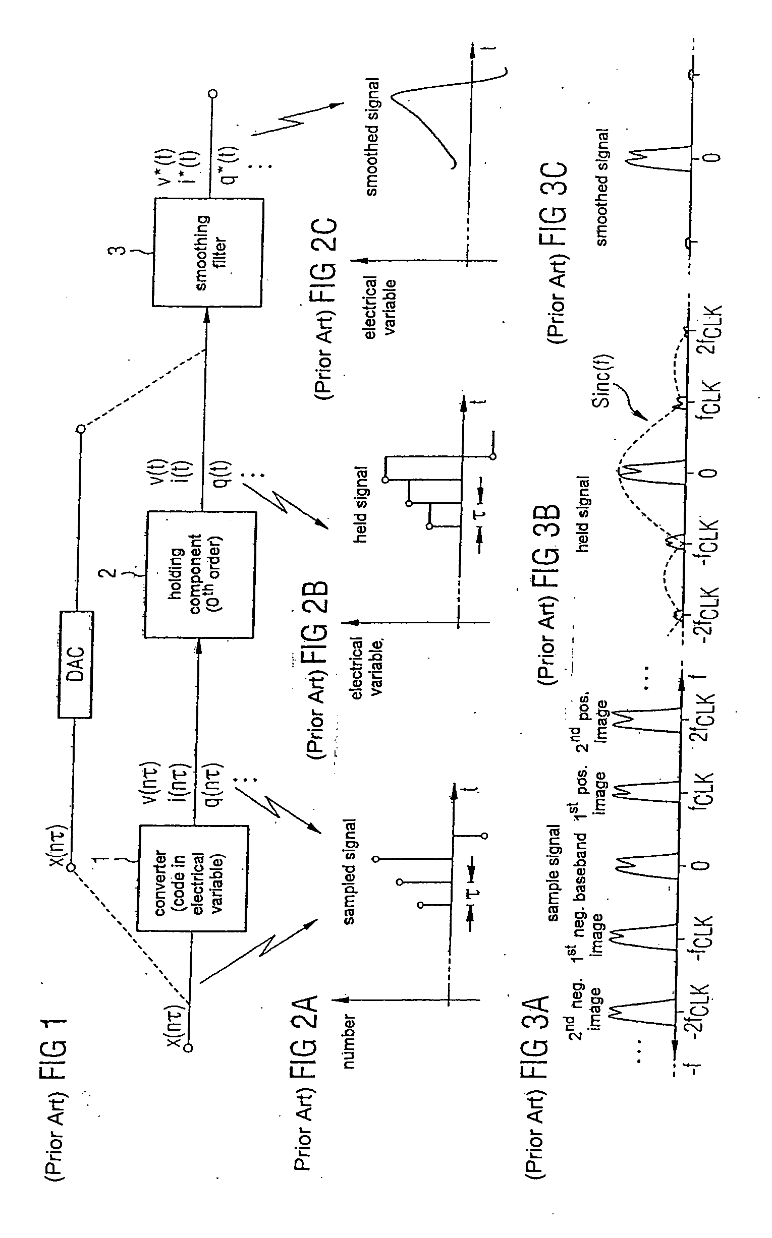
[0037] The clock signal 6 furthermore drives the clock input of the digital / analogue converter 8. The mode of operation of the digital / analogue converter 8 and of the downstream smoothing filter 3 have already been described in relation to FIGS. 1-3C.
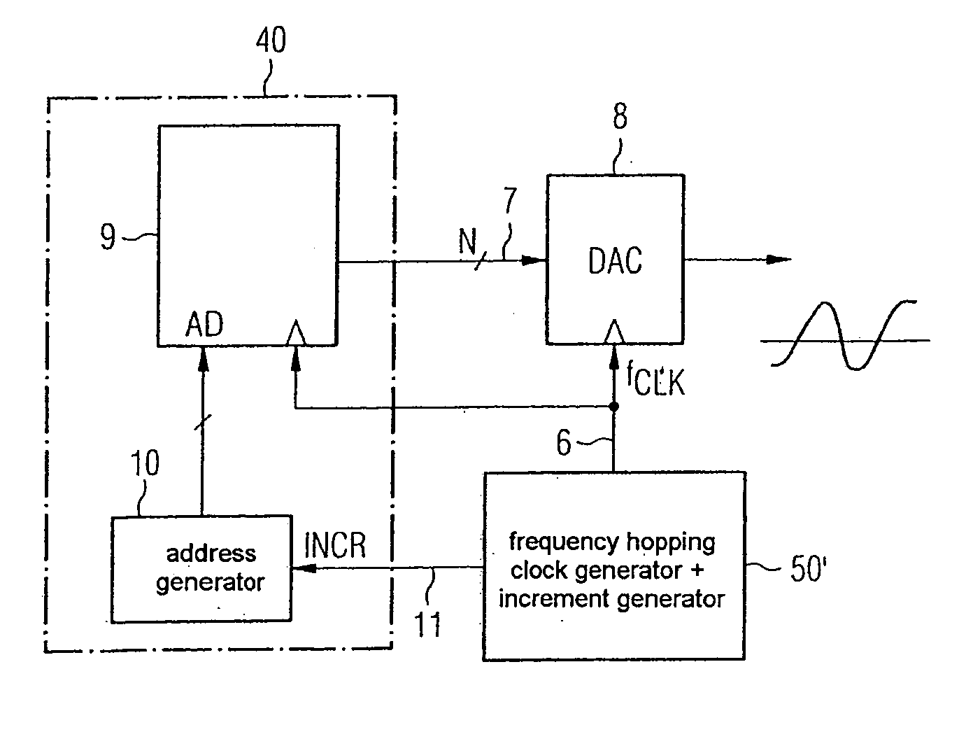
[0038]FIG. 5 shows an exemplary embodiment of a device according to the invention. Components which are the same or ...
PUM
 Abstract
Description
Claims
Application Information
 - R&D
- Intellectual Property
- Life Sciences
- Materials
- Tech Scout
- Unparalleled Data Quality
- Higher Quality Content
- 60% Fewer Hallucinations
Browse by: Latest US Patents, China's latest patents, Technical Efficacy Thesaurus, Application Domain, Technology Topic, Popular Technical Reports.
© 2025 PatSnap. All rights reserved.Legal|Privacy policy|Modern Slavery Act Transparency Statement|Sitemap|About US| Contact US: help@patsnap.com


