Liquid crystal display device, and portable telephone device using liquid crystal display device

Inactive Publication Date: 2005-12-08
PANASONIC CORP
View PDF2 Cites 60 Cited by
  • Summary
  • Abstract
  • Description
  • Claims
  • Application Information

AI Technical Summary

Benefits of technology

[0026] In particular, by disposing the first liquid crystal display part and the second liquid crystal display part on the front and back sides of the second casing, the top and bottom of an image is con

Problems solved by technology

However, such display conversion operation to display is not followed properly when opening/closing of the second casing is carried out quickly.
Such shield parts occupy a predetermined space in the portable telephone device, thus increasing weight of the portable telephone device and requiring a predeterm

Method used


Image

  • Liquid crystal display device, and portable telephone device using liquid crystal display device
  • Liquid crystal display device, and portable telephone device using liquid crystal display device
  • Liquid crystal display device, and portable telephone device using liquid crystal display device

Examples


embodiment 1

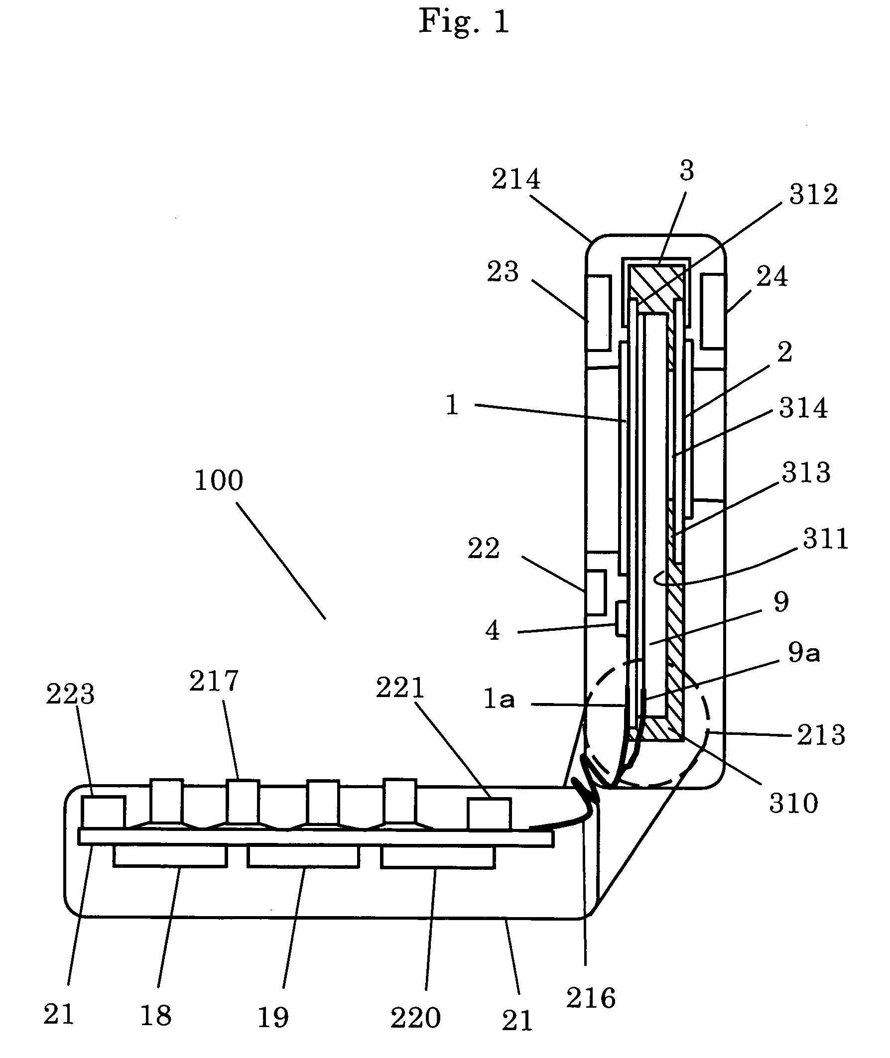
[0048]FIG. 1 illustrates a schematic sectional view of a portable telephone device according to a first embodiment of the present invention. Incidentally, in a configuration of the portable telephone device 100 of the present invention as illustrated in FIG. 1, many parts including a first casing 212 and a second casing 214 are the same as the prior art described before so that the same reference numbers are given to the same parts without further explanation.

[0049] In FIG. 1, a back light 9 is inserted into a first concave 311 of a holder 310 on which a plurality of liquid crystal display parts are formed, while a first liquid crystal display part 1 is inserted into a second concave 312 of the holder 310 located on the top of the back light 9. A driver circuit 4 is located on the first liquid crystal display part 1, one end of the first liquid crystal display part 1 is connected to a flexible connection substrate 3, and the front end of the flexible connection substrate 3 is conne...

embodiment 2

[0072] A portable telephone device according to a second embodiment of the present invention is explained below.

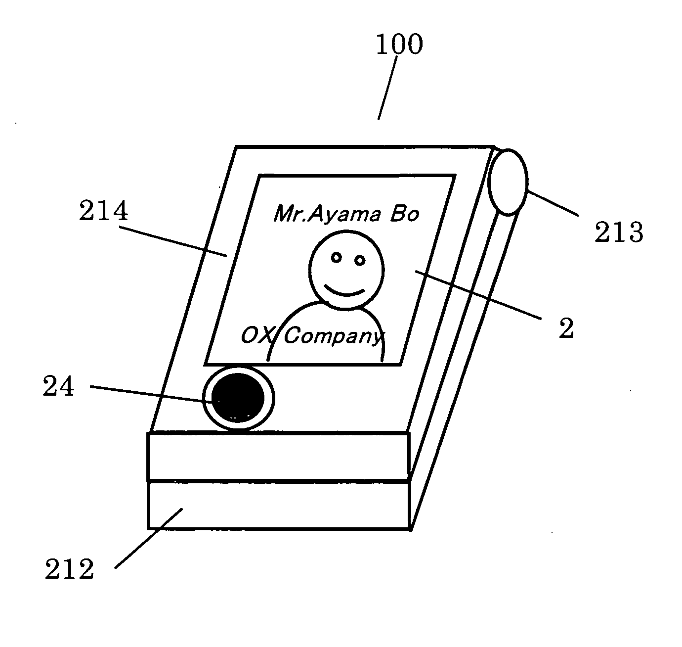
[0073]FIG. 8 is a view illustrating a situation in which Mr. A 60 is trying to photograph a face of Mr. B 61 using a second camera 24 in a portable telephone device 100 according to a second embodiment of the present invention. Mr. A 60 holds a first casing 212 in the portable telephone device 100 in hand and opens a second casing 214 for orienting the camera 24 to Mr. B 61. At this time, the portable telephone device 100 directly displays an image obtained by the second camera 24 in both directions to the first liquid crystal display part 1 and the second liquid crystal display part 2 by means of a display conversion part 42 of a driver circuit 4. Incidentally, to erect the second casing 24 and see the first liquid crystal display part 1 and the second liquid crystal display part 2 on the front and back sides of the second casing 214 means that the top and bottom of an i...

embodiment 3

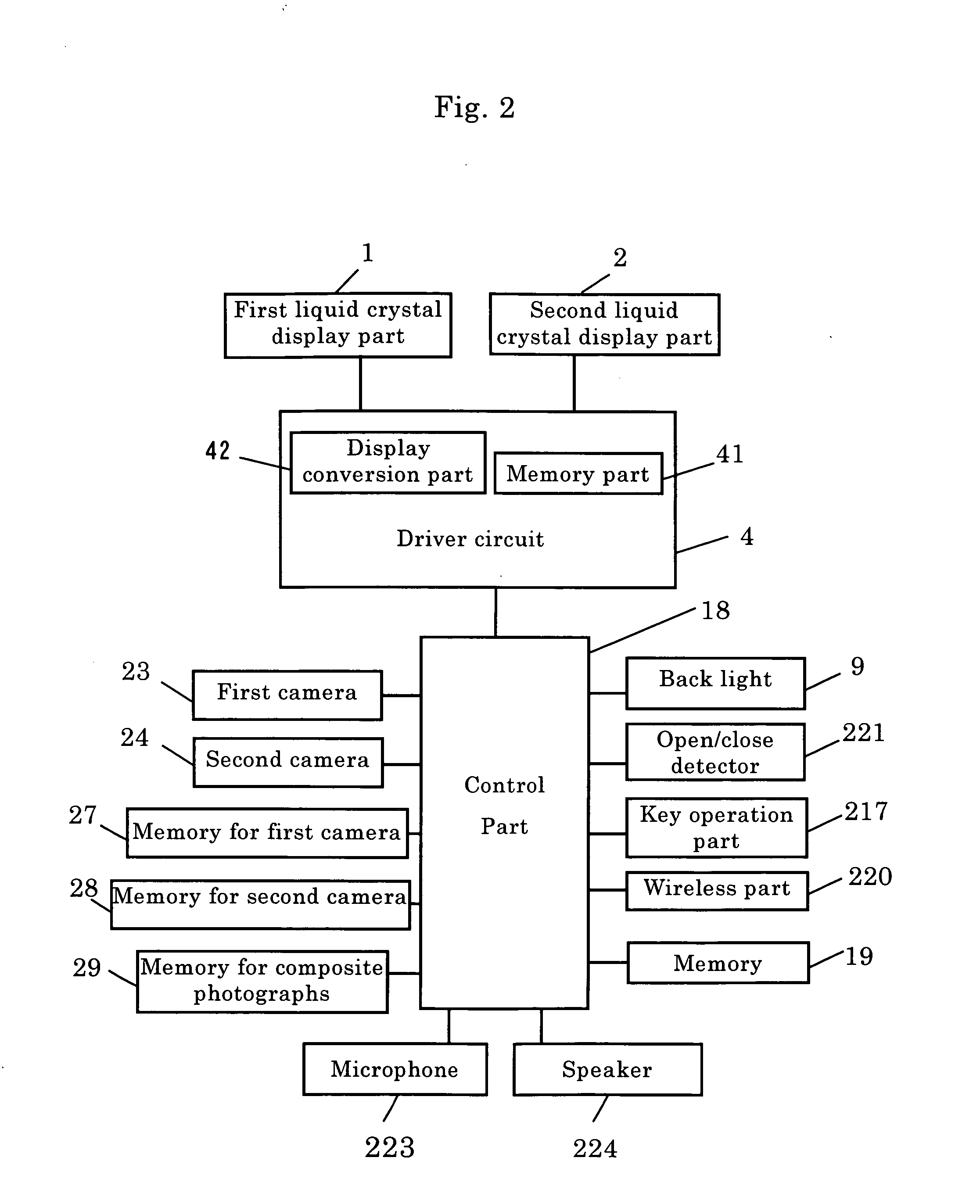
[0076] A portable telephone device according to a third embodiment of the present invention is explained below. In the present invention, as already described in FIG. 1, the first camera 23 and the second camera 24 are mounted on the front and back sides of the second casing 214, and the control part 18 is given a function of combining image information photographed from the first camera 23 and image information photographed from the second camera 24.

[0077] In this manner, image information of Mr. A 60 photographed from the first camera 23 and image information of Mr. B 61 photographed from the second camera 24 can be displayed as combined on a single screen.

[0078]FIGS. 11 and 12 are views illustrating an appearance of the portable telephone device of the present invention when a monitor image 602 of Mr. A 60 on a monitor at the first camera 23 and a monitor image 612 of Mr. B 61 on a monitor at the second camera 24 are displayed as combined on a single screen. FIG. 11 is a view i...


PUM


Abstract

In a fold-up type of portable telephone device, the casing to be opened/closed has liquid crystal display devices on its front and back sides, which causes occurrence of noise. In view of this, in the liquid crystal display device of a portable telephone device, a flexible connection substrate is used to integrally form first and second liquid crystal display parts with a driver circuit shared therebetween. The first liquid crystal display part is connected to the flexible connection substrate to which the second liquid crystal display part is connected. The second liquid crystal display device is formed by adding the flexible connection substrate to the first liquid crystal display part, and both are driven by the driver circuit. Not only an alternative display but also simultaneous displays can be selectively performed.

Description

FIELD OF THE INVENTION [0001] The present invention relates to a liquid crystal display device to be used for a portable telephone device such as a fold-up type of portable telephone device having a plurality of liquid crystal display parts and the like, and a portable telephone device using the liquid crystal display device. BACKGROUND OF THE INVENTION [0002] In a conventional fold-up type of portable telephone device, for example, as described in JP-A-2001-136251, there is known a portable telephone device equipped with a first liquid crystal display device which is seen by an operator at a state that a casing is opened and a second liquid crystal display device which is seen by an operator at a state that a casing is closed. [0003] A schematic sectional view of a conventional fold-up type of portable telephone device 200 is illustrated in FIG. 19. In the fold-up type of portable telephone device 200, a second casing 214 is supported by a hinge 213 in front of an arm extended from...

Claims


Application Information

Patent Timeline
IPC IPC(8): G02F1/13G06F3/14G09G3/36H04M1/02H04M1/57
CPCG02F1/13452G06F3/1423G09G3/3611G09G2300/023G09G2300/0426H04M2250/16H04M1/0214H04M1/0233H04M1/0245H04M1/576G09G2340/0492G02F1/1345H04M1/02
Inventor MIYASHITA, AKIHIROHAKAMATA, KOJIMURAMATSU, FUMIHIROKAWABATA, YOSHIMASANAKANISHI, KIYOSHITSUMURA, TOSHIYUKI
Owner PANASONIC CORP
Why Eureka
Try Eureka