Liquid crystal display device and backlight module thereof

a liquid crystal display and backlighting technology, which is applied in the field of display devices and backlighting modules thereof, can solve the problems of insufficient view angle of liquid crystal display b>1/b>, and insufficient brightness of the central portion, so as to increase the uniformity of the liquid crystal display device and high brightness

Inactive Publication Date: 2005-12-08
PRODISC TECH INC
View PDF12 Cites 138 Cited by
  • Summary
  • Abstract
  • Description
  • Claims
  • Application Information

AI Technical Summary

Benefits of technology

[0011] As mentioned above, the liquid crystal display device and the backlight module according to the invention could control the emitting angle and the emitting direction of the light emitted from the backlight module. Compare to the prior art, the liquid crystal display device and the backlight module according to the invention have the fresnel area with at least one focal point. So, the invention could control the emitting angle and the emitting direction of the emitted l

Problems solved by technology

However, there are two disadvantages in the conventional large-sized liquid crystal display 1.
If the demand of wide view angle is satisfied, the emitted light may be scatted, so that the brightness

Method used


Image

  • Liquid crystal display device and backlight module thereof
  • Liquid crystal display device and backlight module thereof
  • Liquid crystal display device and backlight module thereof

Examples


first embodiment

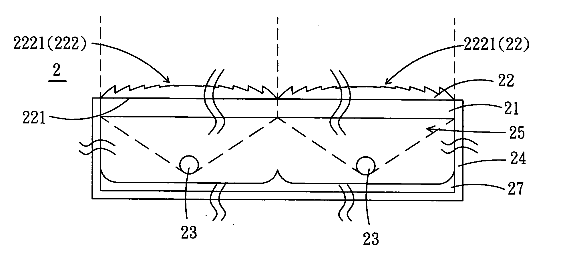
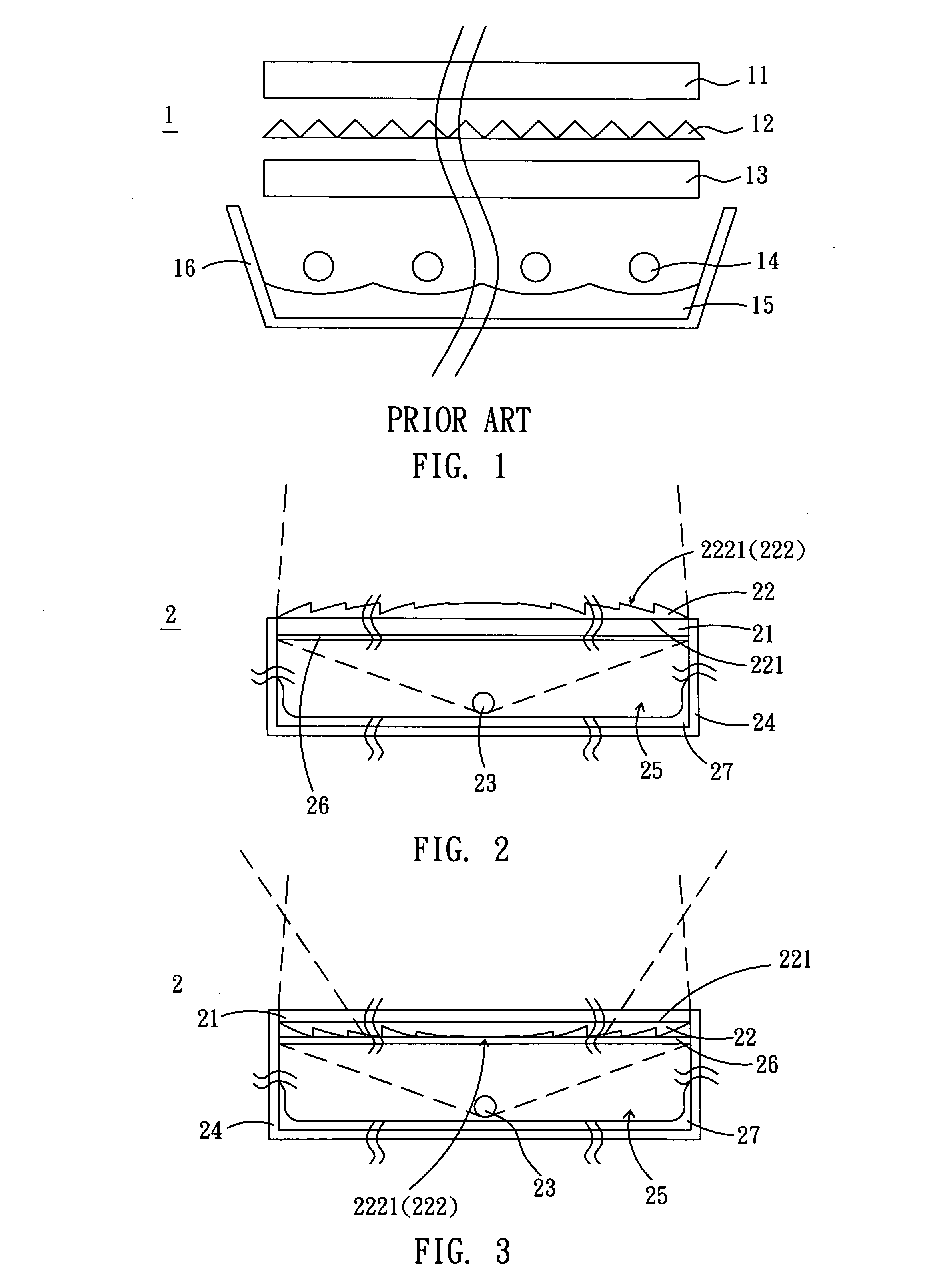
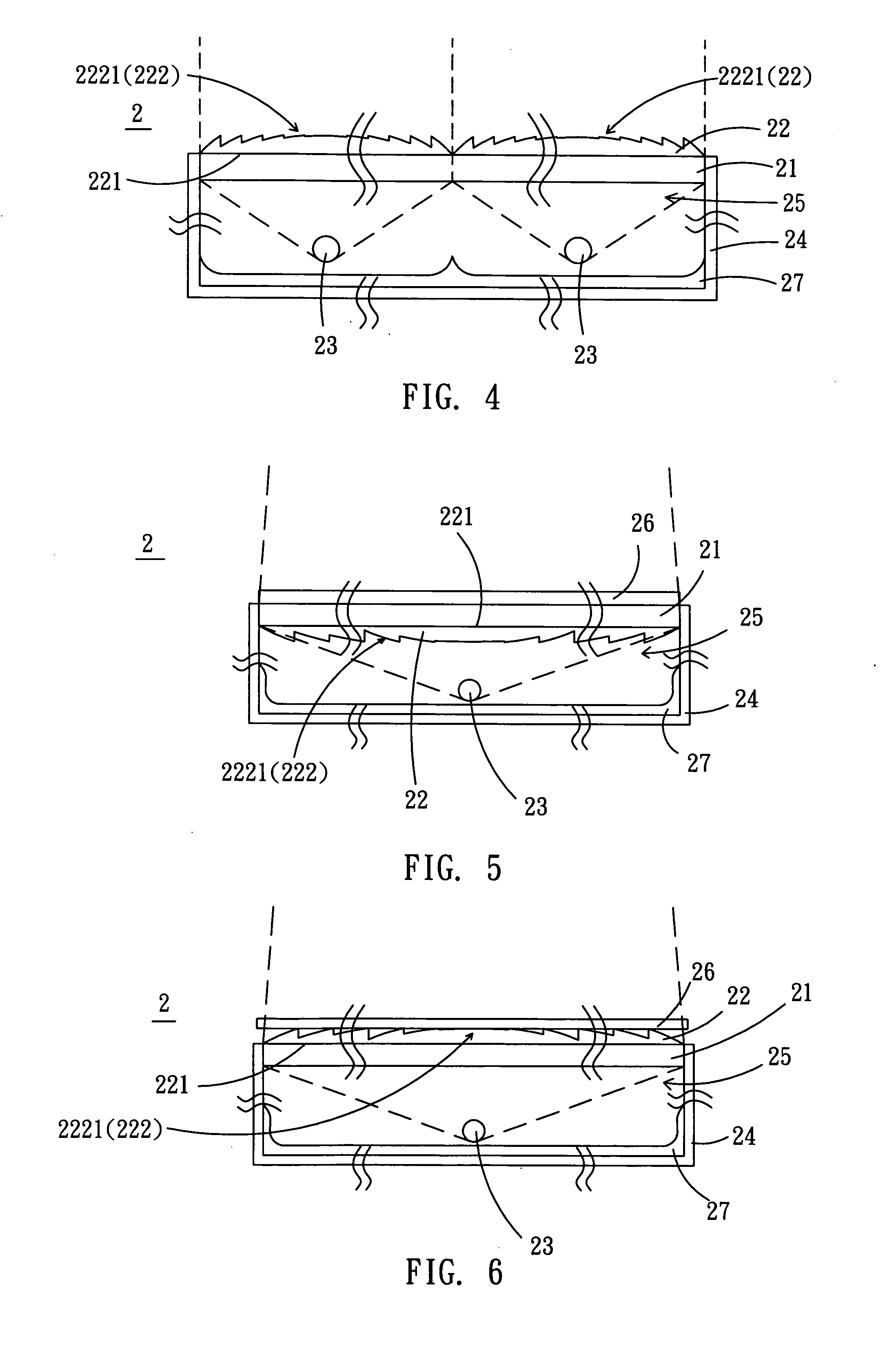
[0020] Please refer to FIG. 2, the backlight module 2 according the first embodiment comprises a light transmissive substrate 21, an optical film 22, and at least one light source 23. In this case, the optical film 22 has a first surface 221 and a second surface 222 opposite to the first surface 221. The first surface 221 of the optical film 22 is connected to the transparent surface 21, and the second surface 222 of the optical film 22 has at least one fresnel area 2221. The light source 23 is disposed at one side of the light transmissive substrate 21.

[0021] The backlight module 2 according the present embodiment further comprises a casing 24, as shown in FIG. 2. The casing 24 has an opening, and the light transmissive substrate 21 is connected to the opening of the casing 24. A storage space 25 is formed between the casing 24 and the light transmissive substrate 21, and the light source 23 is attached to the casing 24 and disposed in the storage space 25.

[0022] In the present em...

second embodiment

[0037] As shown in FIG. 7, the liquid crystal display 3 according to the invention comprises a liquid crystal module 31, a light transmissive substrate 32, an optical film 33, and at least one light source 34. In this case, the optical film 33 has a first surface 331 and a second surface 332 opposite to the first surface 331. The first surface 331 of the optical film 33 is connected to the transparent surface 32, and the second surface 322 of the optical film 32 has at least one fresnel area 3321, and the light source 34 is disposed at one side of the light transmissive substrate 32 and the light transmissive substrate 32 is disposed between the liquid crystal module 31 and the light source 34.

[0038] In the present embodiment, the liquid crystal display 3 further comprises a casing 35, a diffuser 36 and a reflector 37.

[0039] In the present embodiment, the characteristics and functions of the light transmissive substrate 32, the optical film 33, the light source 34, the casing 35, t...


PUM


Abstract

A backlight module comprises a light transmissive substrate, an optical film, and at least one light source. In this case, the optical film has a first surface and a second surface opposite to the first surface. The first surface of the optical film is connected to the transparent surface, and the second surface of the optical film has at least one fresnel area. The light source is disposed at one side of the light transmissive substrate.

Description

BACKGROUND OF THE INVENTION [0001] 1. Field of Invention [0002] The invention relates to a display device and a backlight module thereof and, in particular, to a liquid crystal display device and a backlight module thereof. [0003] 2. Related Art [0004] In general, since flat display devices are thin, low weight and low power consumption, they are increasingly being used in various applications. Among the various types of flat panel display devices, liquid crystal display devices are widely used for cellular phones, personal digital assistants, portable personal computers, monitors, and liquid crystal televisions, etc. because of their superiority in resolution, color image display, weight, contrast and display quality. [0005] LCD devices use the optical anisotropy by an electric field that is applied across the liquid crystal molecules to produce a predetermined image. A specific orientation can be modified by the electric field that is applied across the liquid crystal molecules. B...

Claims


Application Information

Patent Timeline
IPC IPC(8): F21S2/00F21V5/04F21Y101/02F21Y103/00G02F1/1335G02F1/13357G09F13/04
CPCG02F1/133526G02F1/133611G02F2001/133507G02F2001/133607G09F13/04G02F1/133507G02F1/133607G02F1/1335
Inventor KUNG, TA-KUNLIN, YU-SHENGCHIU, CHANG MOLU, YI-CHUNCHOU, YEN-CHUN
Owner PRODISC TECH INC
Why Eureka
Try Eureka