Continuous liquid stream blender

a technology of continuous liquid and blender, which is applied in the direction of process and machine control, instruments, transportation and packaging, etc., can solve the problems of direct contradictory performance change on a given stream, limitations and constraints, and inability to direct empirical sampling

Inactive Publication Date: 2005-12-08
ODEN MACHINERY
View PDF6 Cites 25 Cited by
  • Summary
  • Abstract
  • Description
  • Claims
  • Application Information

AI Technical Summary

Benefits of technology

[0055] 33. To disclose a unique and novel continuous outflow stream liquids blending method and apparatus wherein numerous methods and apparatus are disclosed for validating the performance of the liquids blending invention, and for continuously verifying the performance of the invention, and for safeguarding against undetected malfunctions of the constituent devices comprising the invention.

Problems solved by technology

Although the design taught by Phallen represents an advancement in the state-of-the-art and has had commercial success, limitations and constraints have emerged.
Moreover, the performance change on a given stream is directly contradictory to the setpoint requirements of the other flow streams.
Thus a significant flow rate adjustment must be made for correct dose flow into the kinetic mixing chamber, and direct empirical sampling is not possible.
Another limitation of the Phallen invention is a direct consequence of the hydraulic design.
These types of mixing devices, by their nature, impose a substantial flow restriction and, thus, create a high back pressure.
This condition is unfavorable to best ratio dosing accuracy, stability, and repeatability of the ratio dosing pumps.
Further, induced back pressures are difficult to predict as a function of changing liquid formulas and constituent liquid components and of changing flow rates and conditions.
This problem can be particularly severe where high viscosity liquids are generally harder to mix together and require more mixing elements for thorough combining.
This, in turn, causes a dramatic increase in flow resistance and back pressure acting on the streams ratio dosing pumps.

Method used


Image

  • Continuous liquid stream blender
  • Continuous liquid stream blender
  • Continuous liquid stream blender

Examples


Embodiment Construction

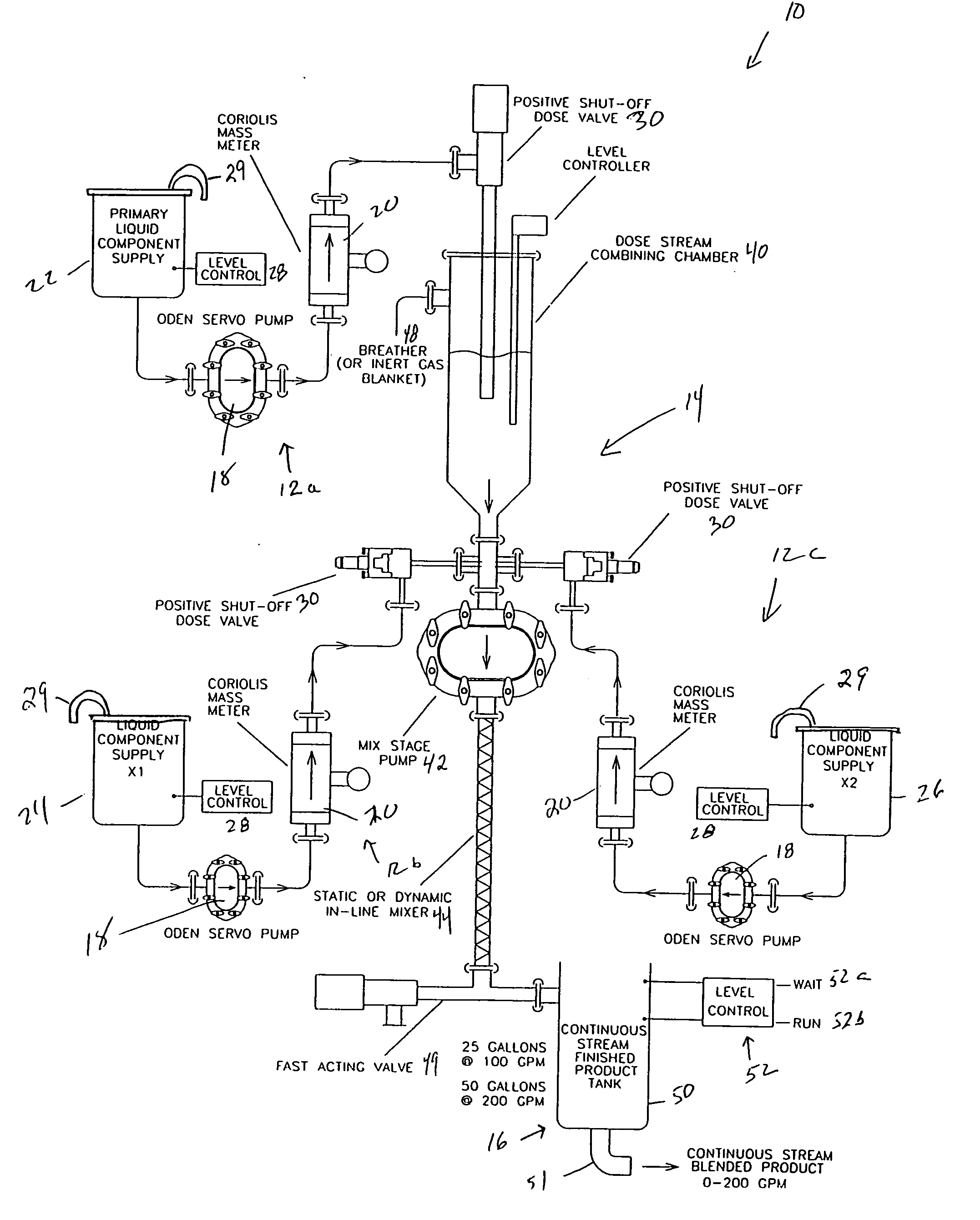
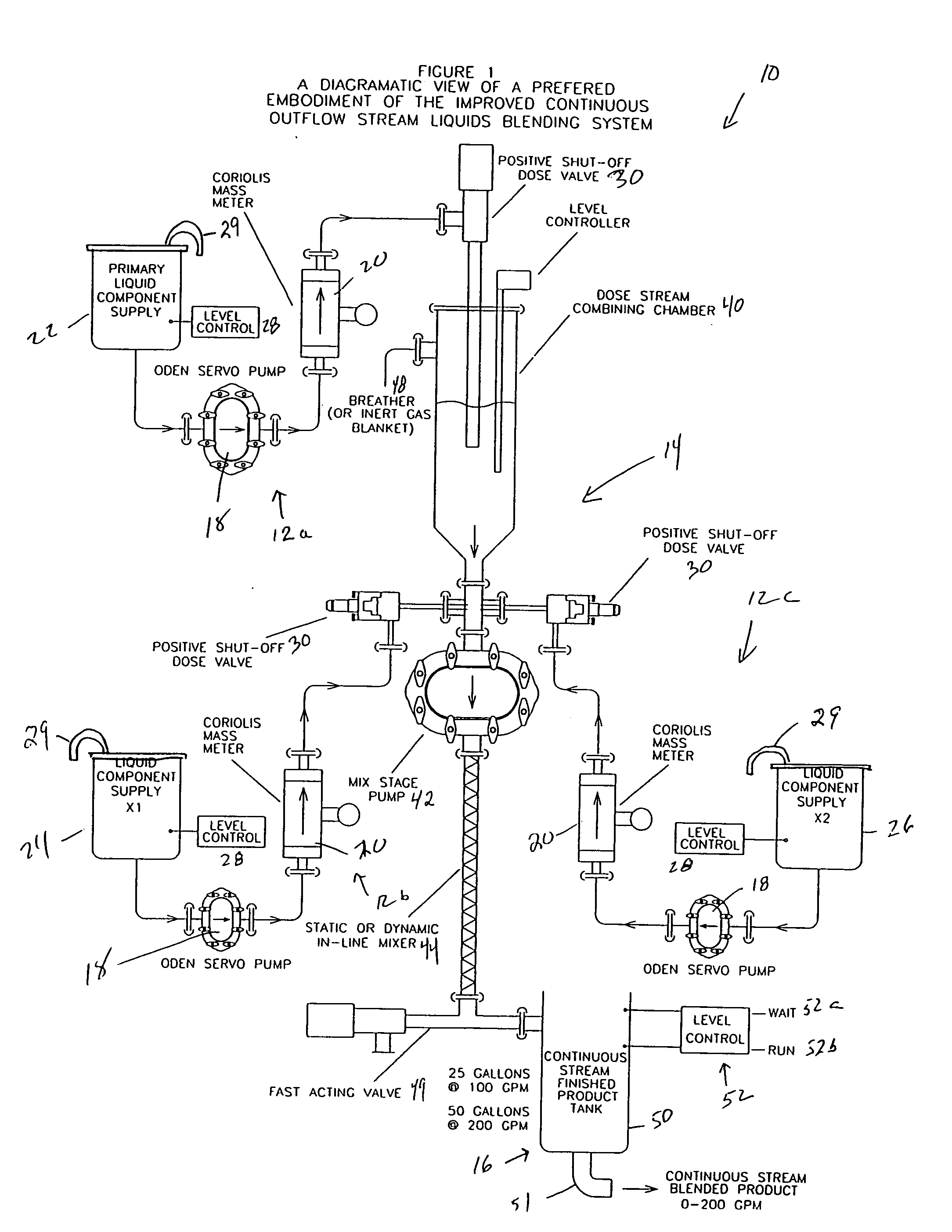
[0071] By definition, a continuous stream blending system, which is indicated generally at 10 in various FIGS., must make fully mixed or blended liquid product available at its output at a makeup rate equal to take-away demand. The take-away demand rate is generally defined by the running speed of the liquid product packaging line being serviced by the continuous stream blending system. The system 10 includes a first streams ratio dosing subassembly, a second stage streams combining and mixing subassembly; and a third finished blended product tank. The first streams ratio dosing subassemblies or digital stream ratio channels or subassemblies are indicated 12, there being one for each liquid component supply. Thus, in FIG. 1, three streams ratio dosing subassemblies are illustrated, subassembly 12a being for a primary liquid component, subassembly 12b being for a first liquid component to be added, and subassembly 12c being for a second liquid component. The second stage streams comb...


PUM

PropertyMeasurementUnit
cycle timeaaaaaaaaaa
volumeaaaaaaaaaa
volumeaaaaaaaaaa

Abstract

Continuous stream ratio blending of two or more liquids. Each stream flow is time synchronized to all others and turned on and off to dose precise ratios into a constant pressure streams combining chamber. Combined on-off flows constitute a net flow rate exceeding some maximum continuous flow demand for the blended liquids. Dosed streams are pumped from the streams combining chamber at a rate matching their inflow, then through a mixing element into a finished blend tank. Use of a constant pressure streams combining chamber feeding a mix pump allows decoupling of individual streams ratio dosing flows and pressures one from another and from the combined stream. Blended liquid is available on demand as a continuous stream from the level controlled finished blend tank. The level sensor automatically starts and stops blended flow into the tank. Streams flow can be stopped upon completion of any dose cycle.

Description

TECHNICAL FIELD [0001] The present invention relates generally to a method and apparatus for the combining together of two or more liquids to form a batch or blend of desired mixture ratio or proportions. More specifically, the invention relates to the use of intermittently operated servo driven pumps, flow meters, and precise fast-acting flow shut-off devices to create repeated time synchronized ratio defined doses of two or more liquids flowing into a common constant pressure streams combining chamber. The synchronized intermittent doses are synchronously removed from the combining chamber at a flow rate matching the summed flow rate of the doses flowing into the chamber and are then displaced through a mixing element. The mixed streams are then received by a final blend tank of desired capacity where the blended liquids are available for use on a continuous stream or flow basis, at a rate up to a defined maximum. The entire apparatus may be started at will and stopped at the comp...

Claims


Application Information

Patent Timeline
Patent Type & Authority Applications(United States)
IPC IPC(8): B01F25/60G05D11/00
CPCB01F3/08B01F15/042G05D11/008B01F23/40B01F35/8311
Inventor PHALLEN, IVERMESSING, DAVIDCOMFORT, ROBERT
Owner ODEN MACHINERY
Why Eureka
Try Eureka