
Camera

Inactive Publication Date: 2005-12-08
FUNAI ELECTRIC CO LTD
View PDF1 Cites 2 Cited by
  • Summary
  • Abstract
  • Description
  • Claims
  • Application Information

AI Technical Summary

Benefits of technology

[0007] The present invention has been made to solve the above-described problems, and an object thereof is to provide a highly operable easy-to-use camera having a simple configuration without losing a locking function.

Problems solved by technology

In such an arrangement, when a rotary operation dial is rotated by an accidental force to result in a switching of the photographing mode, there may be brought an unintended result, which can be a cause of trouble in a worse case.
However in accordance with the arrangement according to the foregoing patent document, the push button for releasing the lock lever is provided next to the rotary operation dial in the same plane, and the rotary operation dial is required to be operated while pressing the push button in the same plane, which naturally requires two-hand control, resulting in poor operationality.
There has particularly been a problem that in the case of a small digital camera, it is difficult to hold the camera body, and therefore two-hand control in the same plane is extremely inconvenient.

Method used


Image

  • Camera
  • Camera
  • Camera

Examples


Embodiment Construction

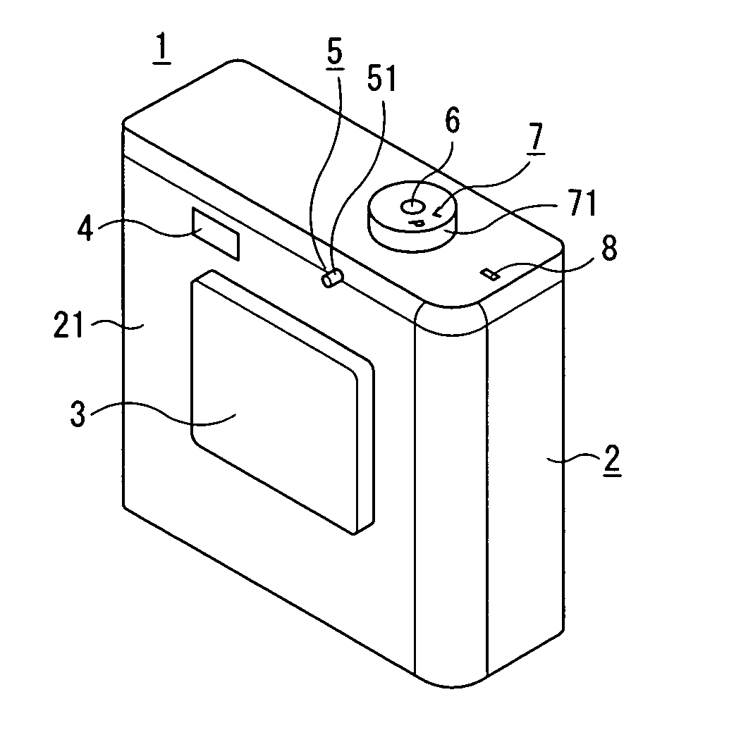
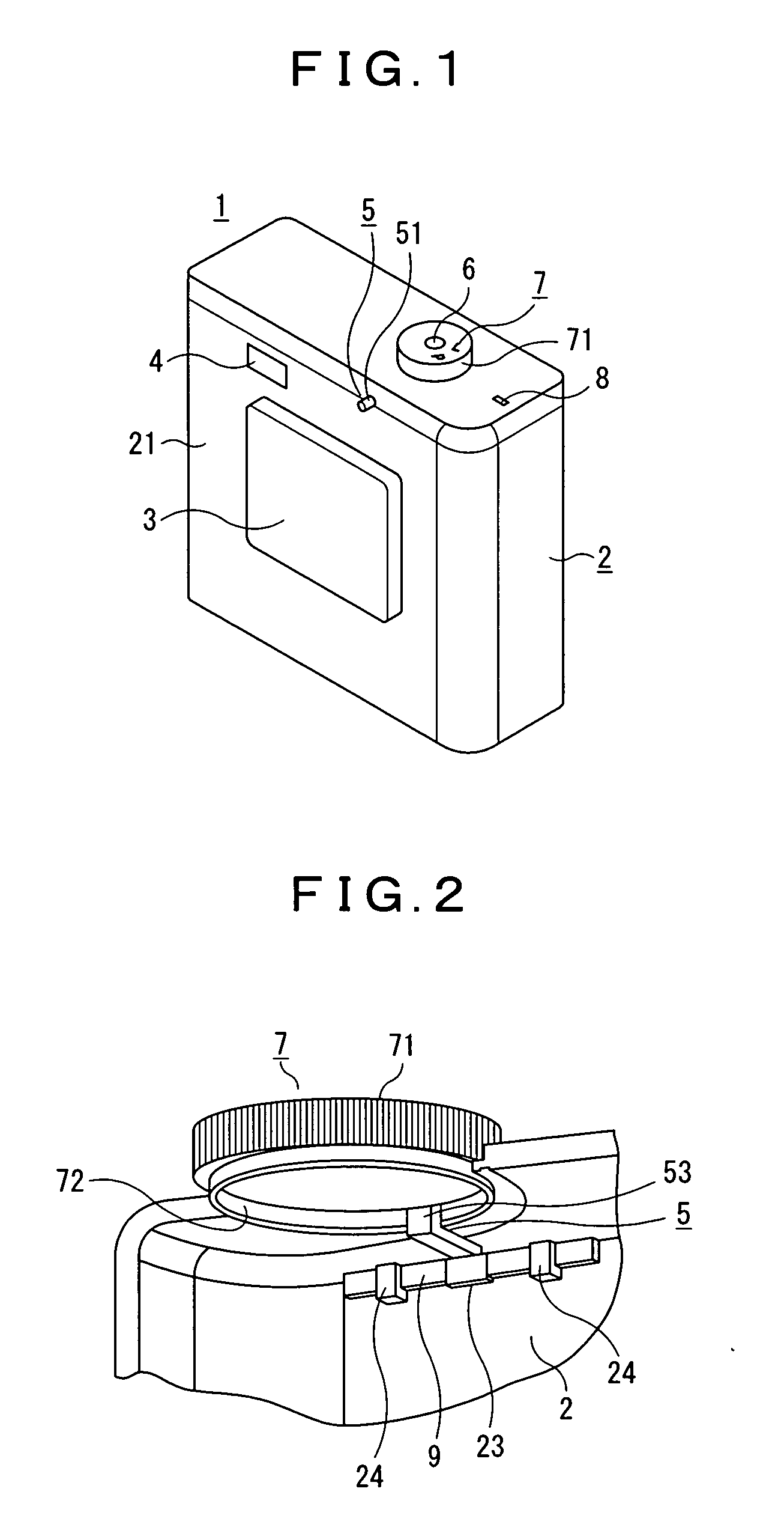
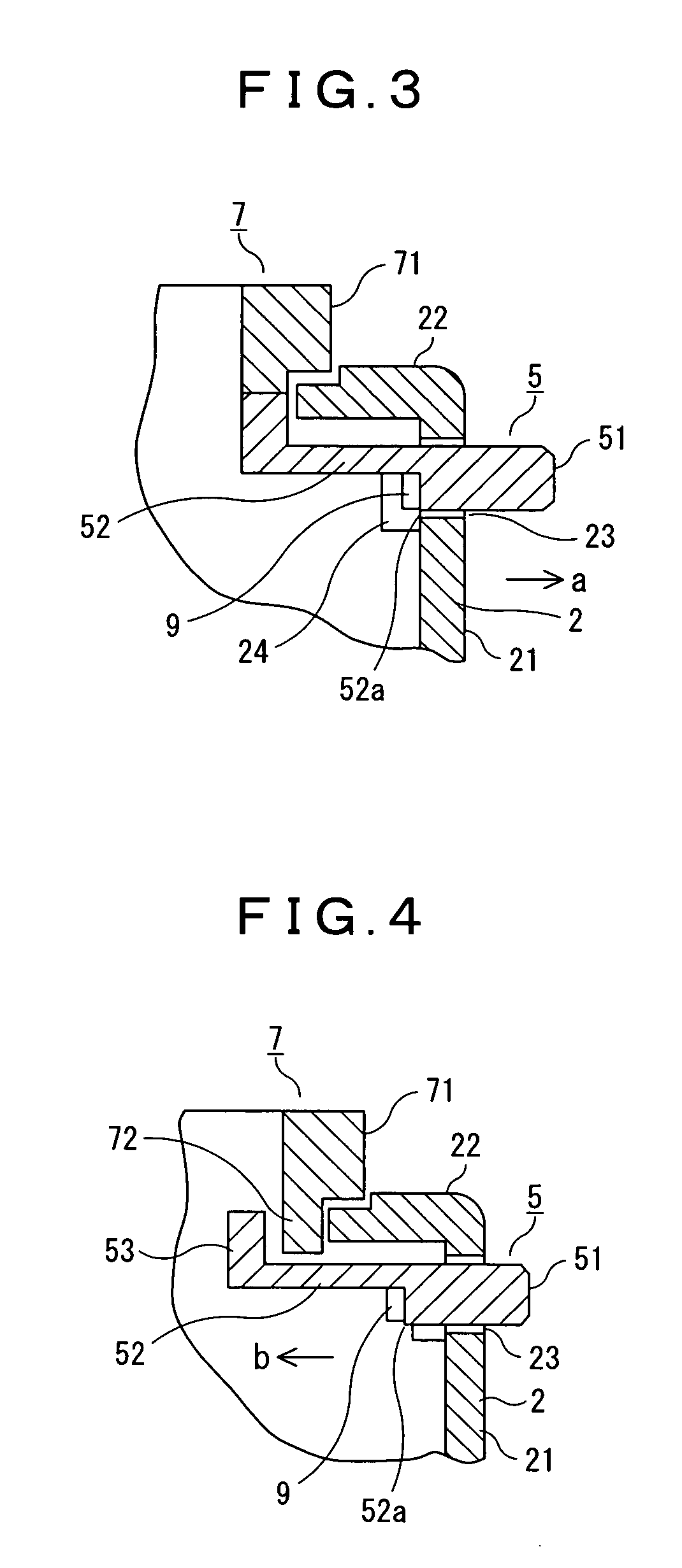
[0031] In a camera comprising: a rotary operation dial to be operated rotationally; a lock arm for locking the rotary operation dial relative to a predetermined position; and a body case to be fitted with the rotary operation dial and the lock arm, a rotary operation portion of the rotary operation dial and a button operation portion of the lock arm are disposed in proximity to each other, respectively, on the upper face side and the back face side of the body case; a lock groom formed in a predetermined position of a lower face rib of the rotary operation dial, the lower face rib lying inside the body case, is arranged in such a manner that a fitting portion of the lock arm can be fitted thereinto; and an urging means for urging the lock arm from inside to outside of the body case is provided.

[0032] An embodiment of the present invention will hereinafter be described with reference to FIGS. 1 to 5. FIG. 1 is a perspective view showing a schematic configuration of a camera having a...


PUM


Abstract

The present invention provides a highly operable easy-to-use camera having a simple configuration without losing a locking function. In a camera comprising: a rotary operation dial 7 to be operated rotationally; a lock arm 5 for locking the rotary operation dial 7 relative to a predetermined position; and a body case 2 to be fitted with the rotary operation dial 7 and the lock arm 5, a rotary operation portion 71 of the rotary operation dial 7 and a button operation portion 51 of the lock arm 5 are disposed in proximity to each other on adjacent faces of the body case 2; a lock groom 73 formed in a predetermined position of a lower face rib 72 of the rotary operation dial 7, the lower face rib 72 lying inside the body case 2, is arranged in such a manner that a fitting portion 53 of the lock arm 5 can be fitted thereinto; and an urging means 9 for urging the lock arm 5 from inside to outside of the body case 2 is provided.

Description

BACKGROUND OF THE INVENTION [0001] 1. Field of the Invention [0002] The present invention relates to a camera having a locking function for locking a rotary operation dial to be operated rotationally, such as a mode setting dial, relative to a rotational predetermined position, and particularly aims at improving its operationality. [0003] 2. Description of the Prior Art [0004] As is well known, a camera employs rotary operation dials such as a mode setting dial, shutter speed setting dial, and exposure compensation value setting dial so that the selection among a plurality of setting information can be operated at the same section. In such an arrangement, when a rotary operation dial is rotated by an accidental force to result in a switching of the photographing mode, there may be brought an unintended result, which can be a cause of trouble in a worse case. [0005] In consideration of the above-described points, there has conventionally been known an arrangement that a push button i...

Claims


Application Information

Patent Timeline
IPC IPC(8): G03B17/02G03B17/00
CPCG03B17/02Y10T70/5765
Inventor KISHII, DAISUKE
Owner FUNAI ELECTRIC CO LTD
Learn More