
Spectral shaping for optical OFDM transmission

Inactive Publication Date: 2005-12-08
RPX CLEARINGHOUSE
View PDF11 Cites 102 Cited by
  • Summary
  • Abstract
  • Description
  • Claims
  • Application Information

AI Technical Summary

Benefits of technology

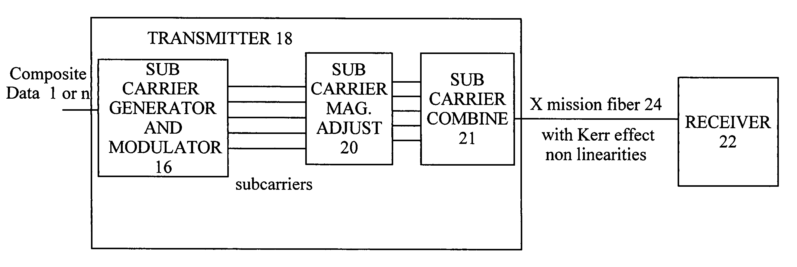
[0012] According to a first aspect of the present invention, there is provided a transmitter for an optical transmission system arranged to transmit onto an optical transmission path, an optical sub carrier multiplexed signal comprising a number of sub-carriers in a band, the path having impairments causing differing error rates for different ones of the sub-carriers, the error rates contributing to an aggregate error rate for the band, and the transmitter being arranged to selectively differentiate the sub-carriers to reduce differences between the contributions to the aggregate error rate.
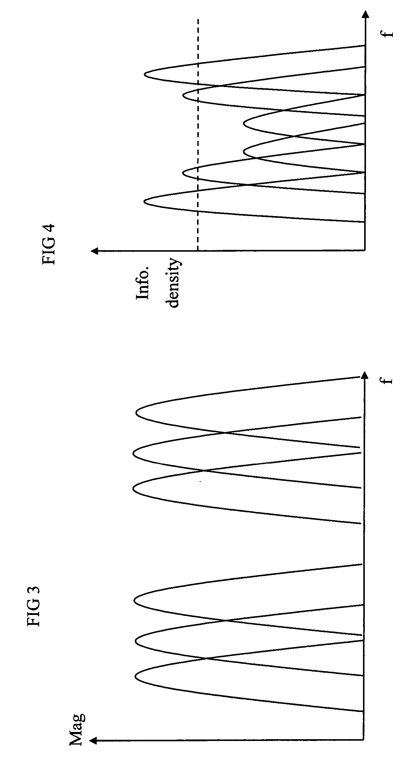
[0050] Another aspect provides a receiver for receiving an optical sub carrier multiplexed signal comprising a number of sub carriers, with different ones of the sub-carriers being modulated with data differently, the receiver having a demodulator for demodulating the different sub carriers. This can enable different information densities and different susceptibility to noise. This can be used to enhance reliability of some sub carriers, or to even out the error rates across the sub carriers for example.

Problems solved by technology

Chromatic Dispersion can cause skewing of the subcarriers, so if no compensation of Chromatic Dispersion is attempted or if the cyclic prefix is shorter than the maximum delay spread, the outer channels experience the greatest error in alignment, hence increased eye closure at the receiver and hence higher error rates (due to CD).
Furthermore both Polarisation Dispersion and Chromatic Dispersion in a direct detection system, can result in nulls elsewhere within the spectrum.

Method used


Image

  • Spectral shaping for optical OFDM transmission
  • Spectral shaping for optical OFDM transmission
  • Spectral shaping for optical OFDM transmission

Examples


Embodiment Construction

[0070] The embodiments described involve optical communication utilising Sub carrier Multiplexing (SCM) and digital signal processing. This will now be described by way of introduction to the embodiments. The use of SCM transmission in an optical communication system can allow the symbol rate to be reduced, thus increasing tolerance to Chromatic Dispersion (CD) and Polarisation Mode Dispersion (PMD), allowing increased reach. Furthermore the use of digital signal processing can reduce the need for many sets of apparatus at the transmitter to generate the sub-carriers, compared to analogue SCM generation techniques, and can reduce the guard bands conventionally required between sub-carriers, and hence improve spectral efficiency.

[0071] Digital signal processing in the receiver can enable the sub carrier spacing to be reduced, such that the sub-carriers overlap, thus improving spectral efficiency. Sub-carriers are spaced at an integer multiple of 1 / (the symbol period of the sub-carri...


PUM


Abstract

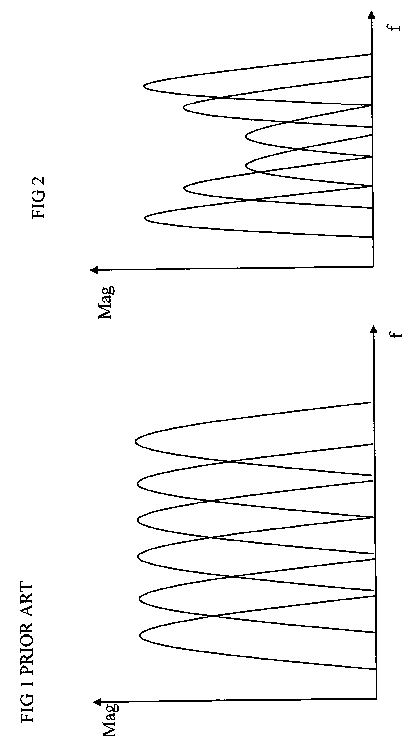
A transmitter for an optical transmission system transmits an optical sub carrier multiplexed signal comprising number of sub-carriers, onto an optical transmission path, and provides spectral shaping by different magnitudes of the sub-carriers, or different modulation formats for different sub carriers. This spectral shaping can reduce performance degradation by Kerr effect optical non linearities. This can mean higher input powers may be launched. The magnitudes can provide a signal spectrum which is lower near a centre of a band of sub carriers than near an edge of the band. Such spectral shaping can be provided in the receiver either to undo the pre emphasis in the transmitter, or to reduce non linearities from components at the receiving side.

Description

RELATED APPLICATIONS [0001] This invention relates to U.S. patent application entitled “Optical Sub carrier Multiplexed Transmission”, Ser. No. 10 / 679,824 filed on 6 Oct. 2003, and its corresponding international patent application, filed on 14 Sep. 2004, (Nortel Networks files 16231ID), and U.S. patent application entitled “Reference phase and amplitude estimation for coherent optical receiver” Ser. No. 10 / 780,430 filed on 17 Feb. 2004, (Nortel Networks file 16549ID), all three of which are incorporated herein by reference in their entirety.FIELD OF THE INVENTION [0002] This invention relates to transmitters, receivers, other components of communications systems, to corresponding methods and software, and to methods of offering a transmission service over such apparatus. BACKGROUND TO THE INVENTION [0003] It is well known in communication systems to communicate data using a carrier signal modulated with the data. In a conventional modulation format, such as amplitude modulation, a ...

Claims


Application Information

Patent Timeline
IPC IPC(8): H04B10/00H04B10/155H04B10/18
CPCH04B10/2543H04B10/58H04B10/548
Inventor KEE, HUAIEPWORTH, RICHARDROBINSON, ALANRICKARD, ROBIN
Owner RPX CLEARINGHOUSE
Learn More