
Shank for a rotary and/or percussion working tool

a percussion and working tool technology, applied in the direction of portable percussive tools, turning devices, stone-like material working devices, etc., can solve the problems of non-uniform noticeable wear of the chuck, increase the diameter of the drill bit, and damage to the interior of the chuck, so as to reduce the axial displacement of the working tool, and reduce the axial displacement

Inactive Publication Date: 2005-12-08
HILTI AG
View PDF6 Cites 5 Cited by
  • Summary
  • Abstract
  • Description
  • Claims
  • Application Information

AI Technical Summary

Benefits of technology

[0012] As a result of the provision of an end shoulder, which is spaced, in the direction toward the working tool-side end of the shank, from the locking shoulder as far as possible, the change in the cross-section of the locking groove first takes place in the vicinity of the working tool-side end of the shank. Thereby, at least in tool with a stem diameter smaller than or equal to the guide diameter, a reflection region having a length of minimum e-time of the guide diameter, where e is the base of a natural logarithm, which reflection region changes the acoustic impedance and, thus, upsets the tansmission of the blow pulse, is avoided. In particular, high torques can be transmitted without causing any damage at smaller guide diameters, which improves blow pulse behavior at small drill diameters.
[0015] Advantageously, an axial guide length between a working tool-side guide end with the guide diameter and the end shoulder of both locking grooves is smaller than 1.5 times of the guide diameter. Thereby, a sufficiently long guide length up to the working tool-side end is realized, with a good blow pulse transmission behavior.
[0017] Advantageously, at least over the contact length, a radial groove depth of each entraining groove amounts to between 0.5 and 1 times of the groove with. Thereby, high torques can be transmitted without a noticeable weakening of the cross-section and with a sufficient web that engages in the entraining groove.
[0018] Advantageously, there are provided at least three entraining grooves which are, advantageously are arranged mirror symmetrically. This insures transmission of high torques.
[0019] Advantageously, the end shoulder of each of the locking grooves is formed by the working tool-side end shoulder of a respective further locking groove which is axially spaced, in the direction toward the working tool-side end of the shank, from the respective locking groove and is separated therefrom. Thereby, there are provided intermediate shoulders that further limit the axial displacement of the working tool in the chuck.

Problems solved by technology

It has been shown that an increase of the drill diameter above 17 mm leads to damages, specifically, to breaking of the shank in the region of a locking groove and to destructions in the interior of the chuck.
Even in the case when during the use of drills having a larger diameter, a break does not take place, a plastic deformation of the shank takes place which leads to a non-uniform noticeable wear of the chuck.
Because of this, working tools are often very difficult to withdraw from a chuck.
Drills with a guide diameter of 18 mm but with a smaller drill diameter of 14 mm have a poor blow transmission.
Furthermore, such unproportional tools are not economically in manufacture.
A multi-year experience has shown that these multiple loads endanger, in particular, the cross-section of the shank in the region of the axial locking end of the shank.
Such tapering, inclined to a radius by 60°, legs are not suitable for transmissions of high torques that occur, in particular, in tool blocks.
In addition, the locking grooves, reduce the leg surface available for transmission of a torque.

Method used


Image

  • Shank for a rotary and/or percussion working tool
  • Shank for a rotary and/or percussion working tool
  • Shank for a rotary and/or percussion working tool

Examples


Embodiment Construction

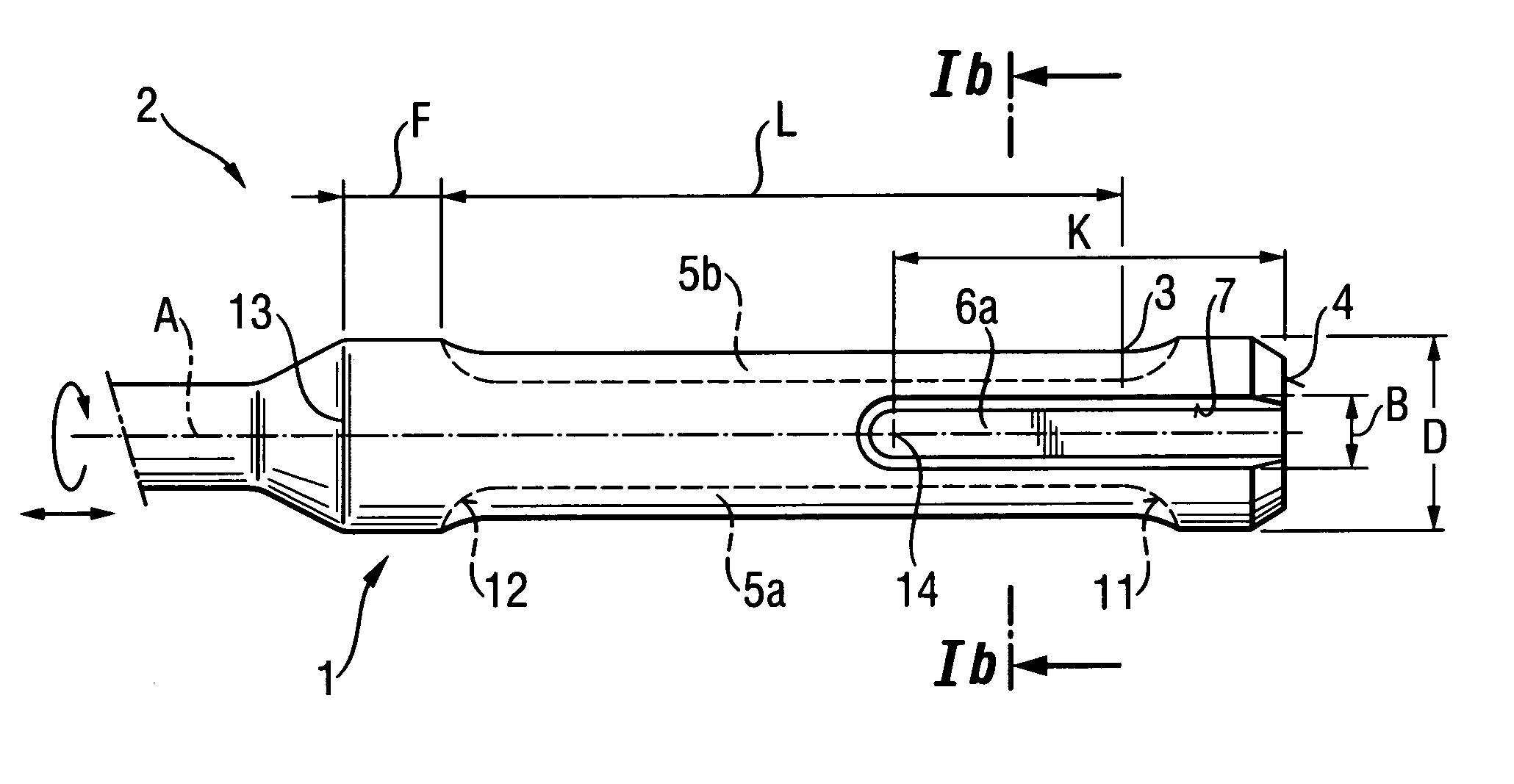
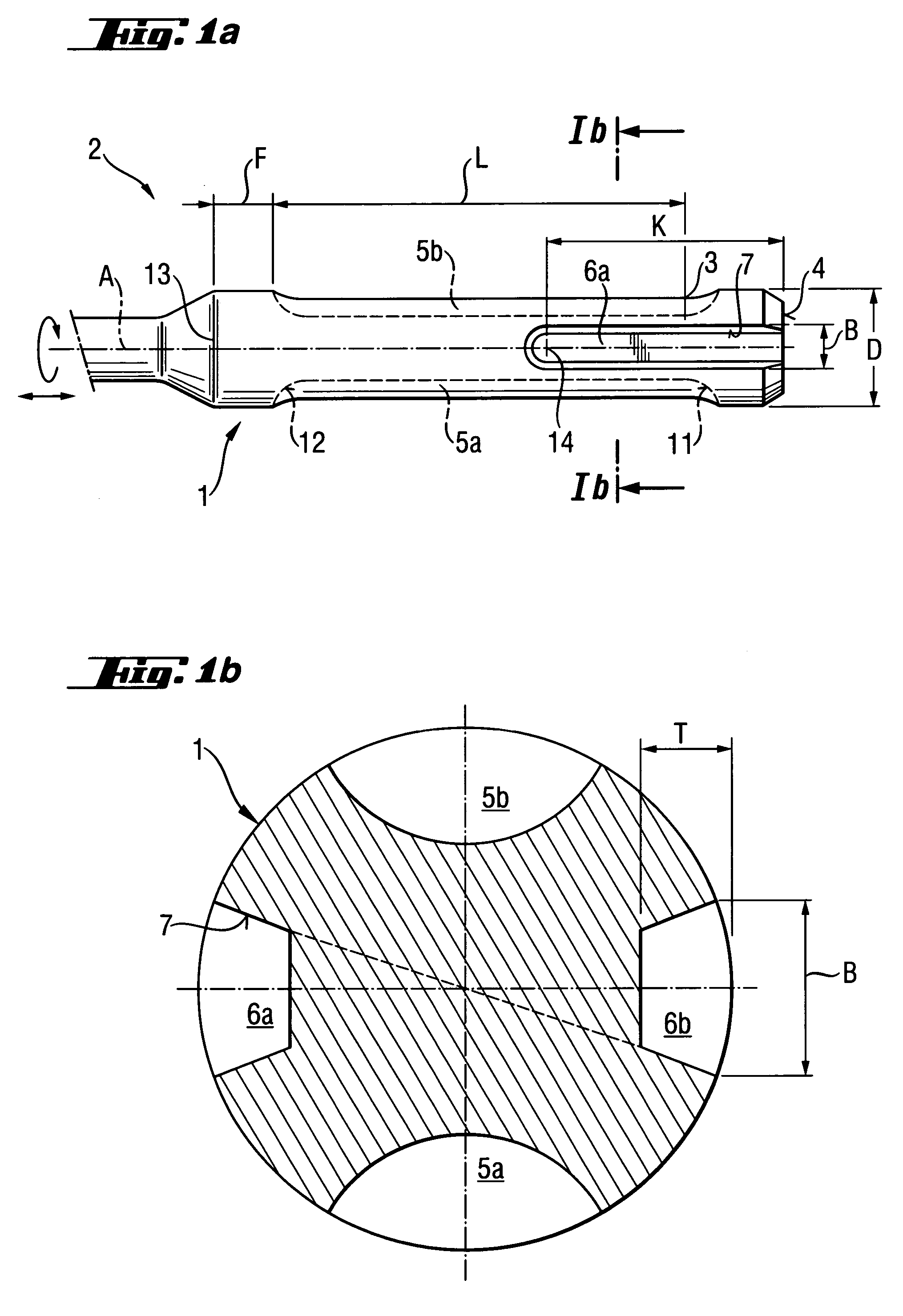
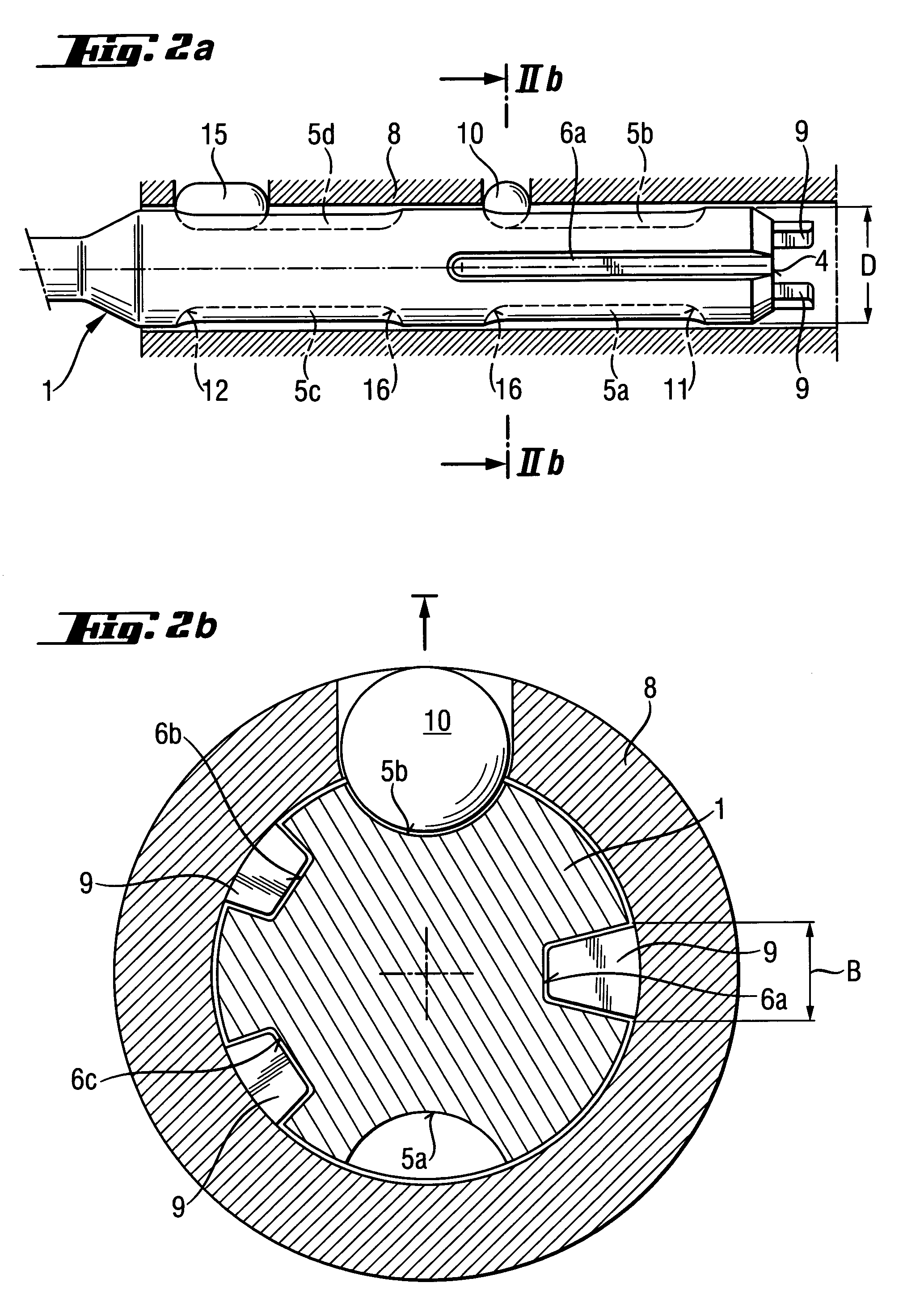
[0027]FIGS. 1a-1b show a shank 1 according to the present invention of a rotary-percussion working tool 2 rotatable about and displaceable along an axis A. The shank 1 has a twofold rotational symmetry and extends along the axis A, with a maximal guide diameter D. The shank 1 has two identical, arranged diametrically opposite each other, locking grooves 5a, 5b. The locking grooves 5a, 5b are provided at an axial locking end 3 with a locking shoulder 11, respectively, remote from a free end surface 4 of the shank 1. The shank 1 further has two entraining grooves 6a, 6b mutually tangentially offset with respect to the locking grooves 5a, 5b and having a tangential groove width B. The entraining grooves 6a, 6b have each a tangential force application surface 7 extending along a contact length K parallel to and transverse to the axis A. Each of the locking grooves 5a, 5b has, at its working tool side, an end shoulder 12 axially spaced from the respective locking shoulder 11. The end sho...


PUM

PropertyMeasurementUnit
diameteraaaaaaaaaa
diameteraaaaaaaaaa
diameteraaaaaaaaaa

Abstract

A shank of a rotary-percussion working tool (2) has at least two, diametrically opposite locking grooves (5a, 5b) each having a locking shoulder (11) at an axial locking end (3) and spaced from a free end surface (4) of the shank (1), and an end shoulder (12) axially spaced from the locking shoulder (11) in a direction of a working tool-side end of the shank (1) and spaced from the axial locking end (3) of the shank (1) by a length (L) amounting at least to three times of a guide diameter (D) of the shank (1), and at least two entraining grooves (6a, 6b) mutually tangentially offset with respect to the locking grooves (5a, 5b), opening toward the free end surface (4), and having a tangential groove width (B) and at least one tangential, force application surface (7) extending over a contact length (K).

Description

BACKGROUND OF THE INVENTION [0001] 1. Field of the invention [0002] The present invention relates to a shank for a rotary and / or percussion working tool such as trepan, chisel, or boring bit for working stone, concrete, or brickwork. [0003] 2. Description of the Prior Art [0004] Generally, a rotary and / or percussion working tool has a shank that extends along the working tool axis and is designed for a rotary and / or percussion hand-held power tool. For a random use of a multiple tool palette, the interface between a tool shank and a chuck of the power tool should be compatible at least within predetermined power classes. The presently used worldwide, in drill hammer systems, practically standardized shanks and associated chucks are disclosed, e.g., in German Publications DE 2552125A1 and DE 3716915A1. The disclosed shanks have a working too-side cylindrical guide surface, locking grooves which are axially closed at their ends adjacent to the free end surface of the shank, and trapez...

Claims


Application Information

Patent Timeline
Patent Type & Authority Applications(United States)
IPC IPC(8): B23B31/02B25D17/08B23B45/16B23B51/00B25D17/02B28D1/14
CPCB25D17/088B25D2217/0042B25D2217/0049Y10T408/907B25D17/02B23B51/00B23B45/00
Inventor KLEINE, WERNERBRITTEN, WERNER
Owner HILTI AG
Learn More