Constant velocity joint

a constant velocity, joint technology, applied in the direction of yielding couplings, rotary machine parts, couplings, etc., can solve the problems of reducing the size and weight of the uj, achieve the effect of suppressing excessive quality, increasing strength against a pressing force from the torque transmitting ball, and reducing the size and weigh

Active Publication Date: 2005-12-08
NTN CORP
View PDF5 Cites 32 Cited by
  • Summary
  • Abstract
  • Description
  • Claims
  • Application Information

AI Technical Summary

Benefits of technology

[0016] The invention, which has been achieved with the above in mind, has a first problem to avoid excessive quality with respect to contact wear, etc., on the outboard side of the cage so as to avoid waste, and then improve the strength of the cage against the pressing force from the torque transmitting balls on the inboard side and accordingly to avoid damage or breakage to the cage. Further, a second problem is to avoid excessive quality of those constituent elements of an UJ which have a low probability of being damaged or broken while sacrificing their durability, and to give consideration so as to fully secure strength for the cage having a high probability of being damaged or broken, thereby attaining size and weight reductions of the UJ.

Problems solved by technology

Further, a second problem is to avoid excessive quality of those constituent elements of an UJ which have a low probability of being damaged or broken while sacrificing their durability, and to give consideration so as to fully secure strength for the cage having a high probability of being damaged or broken, thereby attaining size and weight reductions of the UJ.

Method used


Image

  • Constant velocity joint
  • Constant velocity joint
  • Constant velocity joint

Examples


Embodiment Construction

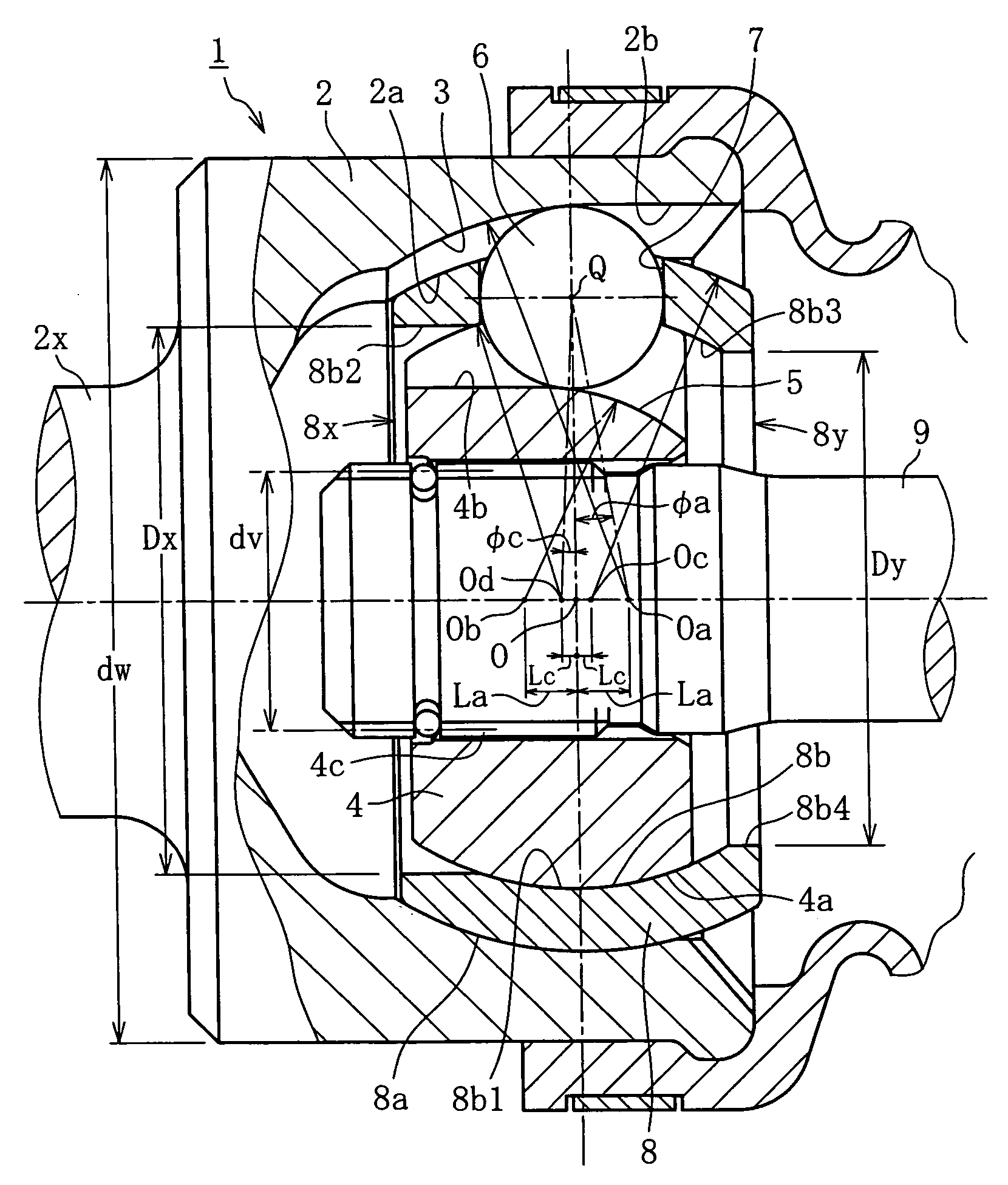
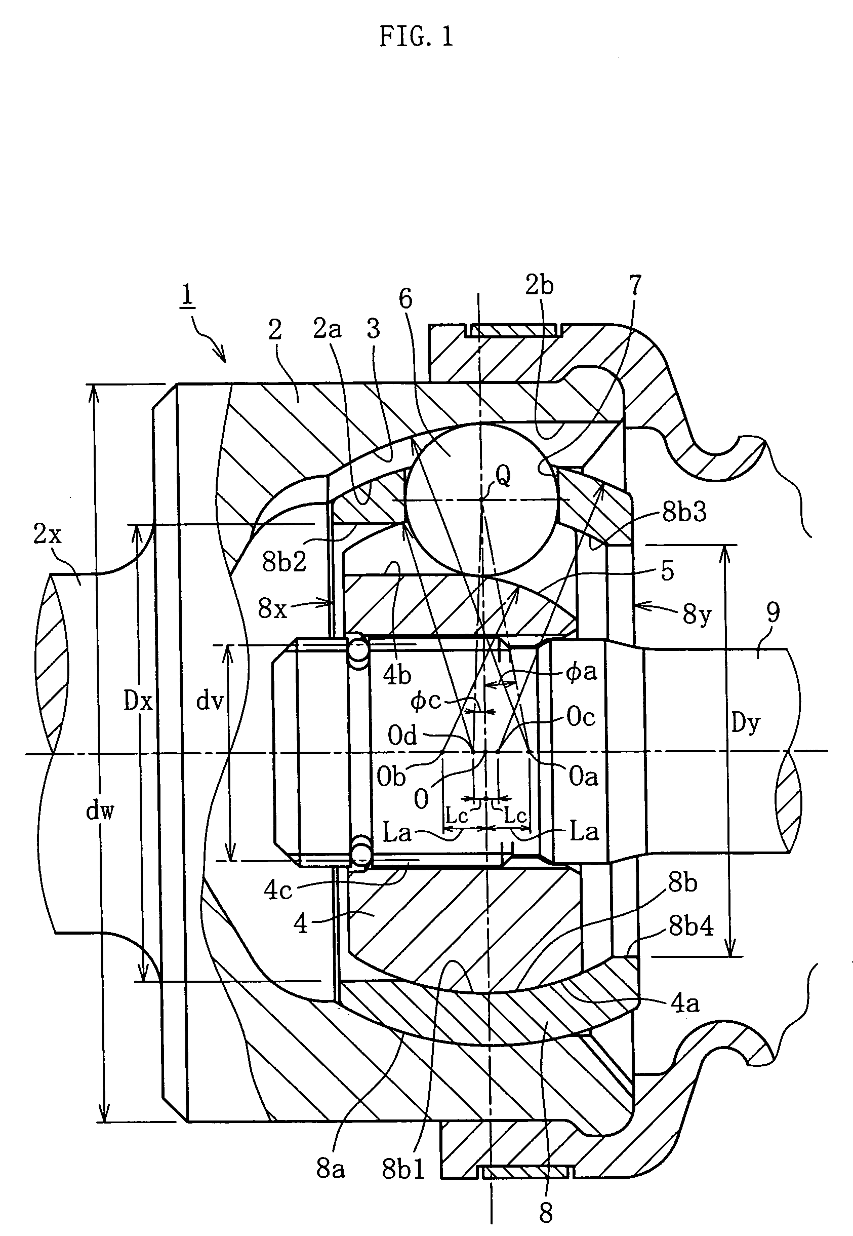
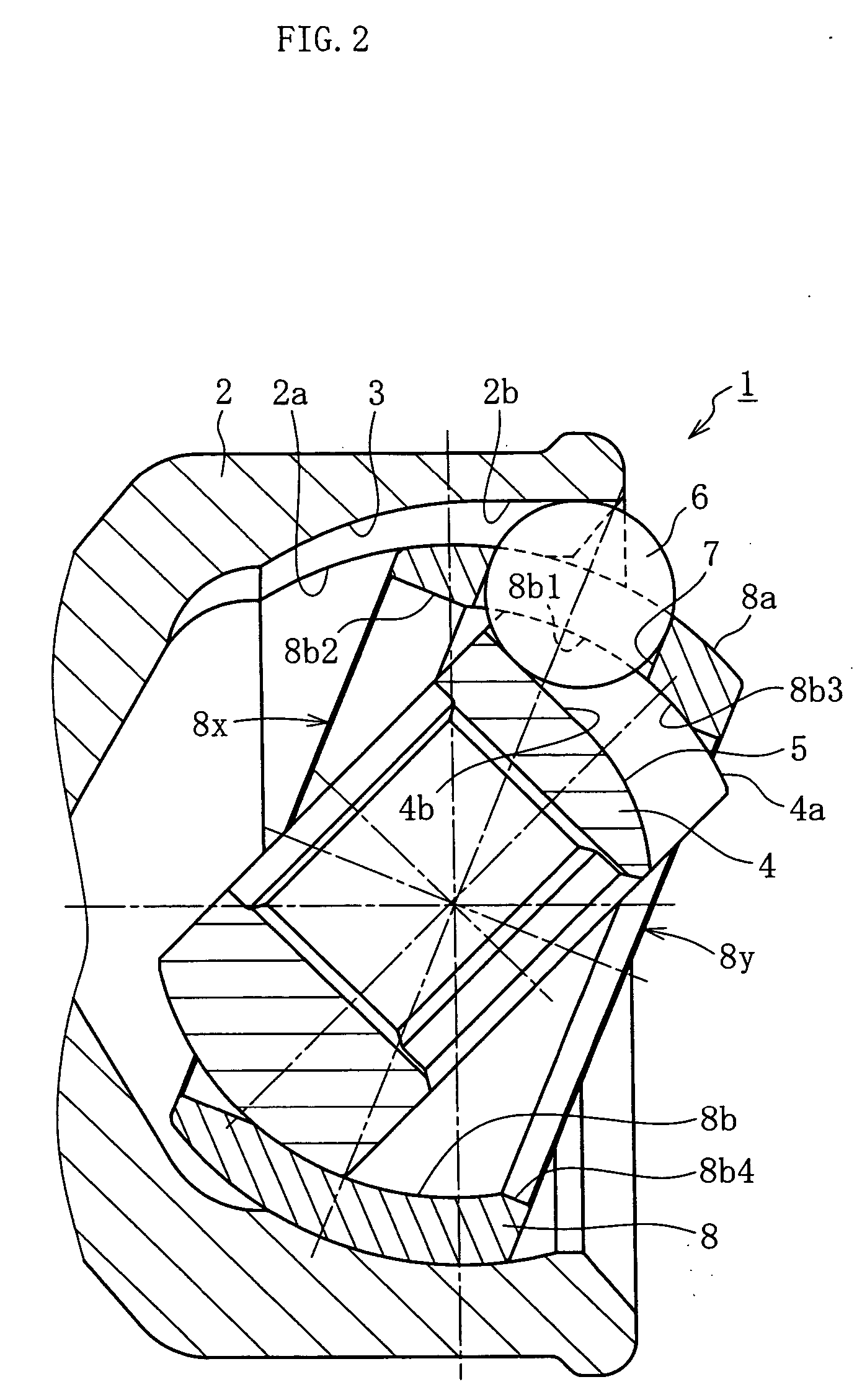
[0050] The embodiments of the invention will now be described with reference to the drawing. In addition, a constant velocity joint according to an embodiment of the invention is the one disposed on the outboard side of the drive axle 26 (27) described on the basis of FIG. 6, while the drive axle is the one, already described with reference to FIG. 7, disposed on the front side (or it may be on the rear side). Therefore, only the constant velocity joint and its peripheral devices will be described hereinafter.

[0051]FIG. 1 illustrates a state assumed when an ATV undercut free type constant velocity joint (UJ) 1 according to an embodiment of the invention takes a working angle θ of 0°. FIG. 2 shows a state assumed when the working angle θ of said constant velocity joint 1 is a maximum working angle (for example, 50°). As shown in these figures, the constant velocity joint 1 comprises an outer joint member 2 (outer ring) with a spherical inner peripheral surface 2a axially formed with...


PUM


Abstract

A constant velocity joint 1 disposed on the outboard side of a drive axle for transmitting drive power to a wheel, comprising an outer joint member 2 having a plurality of track grooves 3 on the spherical inner peripheral surface 2a, an inner joint member 4 having a plurality of track grooves 5 on the spherical outer peripheral surface 4a, torque transmitting balls 6 disposed in a plurality of ball tracks formed by the opposed track grooves 3 and 5 of both joint members 2 and 4, and a cage 8 interposed between both joint members 2 and 4 and receiving and holding the torque transmitting balls 6 in pockets 7, wherein the outboard-side end of the cage 8 is formed with an opening 8x for removably inserting the inner joint member 4 and the inboard-side end is formed with an opening 8y whose diameter is smaller than that of the outboard-side opening 8x.

Description

BACKGROUND OF THE INVENTION [0001] 1. Field of the Invention [0002] The present invention relates to a constant velocity joint, particularly to a constant velocity joint disposed on the outboard side of a drive axle for transmitting drive power to a wheel. [0003] 2. Description of the Prior Art [0004] As is known in the art, in automobiles and other various vehicles similar thereto, constant velocity joints capable of transmitting rotational power at constant velocity even when there is an angular or axial displacement between two shafts have been installed in a power transmission path for transmission of drive power from the engine to a wheel. As an example of a vehicle having such power transmission path, a so-called ATV (All Terrain Vehicle, also called a four-wheeled buggy car) which is an uneven terrain traversing, four-wheeled or three-wheeled mounted type vehicle, equipped with balloon tires and designed to freely traverse wastelands, sandy beaches and the like has come to be...

Claims


Application Information

Patent Timeline
Patent Type & Authority Applications(United States)
IPC IPC(8): F16D3/16F16D3/223
CPCF16D3/223F16D3/2237F16D2003/22303F16D2003/22309Y10S464/906
Inventor NAKAGAWA, TOHRUAZUMA, KAZUHIRO
Owner NTN CORP
Why Eureka
Try Eureka