Gas analyzer calibration checking device

a gas analyzer and calibration checking technology, applied in the direction of sensors, withdrawing sample devices, diagnostics, etc., can solve the problems of affecting the accuracy of the gas analyzer, and affecting the accuracy of the measuremen

Inactive Publication Date: 2005-12-08
EXALENZ BIOSCIENCE LTD
View PDF44 Cites 46 Cited by
  • Summary
  • Abstract
  • Description
  • Claims
  • Application Information

AI Technical Summary

Benefits of technology

[0010] The present invention seeks to provide new methods and devices for ensuring the accuracy and reliability of breath tests, by the use of system and calibration checking devices, optionally incorporating filtering devices, and methods of ensuring their periodic use.
[0013] The present invention first of all seeks to provide a new system checking device for use with gas analyzer-based breath test instrumentation, including the ability to perform a calibration check of the instrument against known calibrating gases. The use of the device with breath tests is particularly important, because of the high sensitivity, selectivity and accuracy, which must be maintained to ensure the success of such tests. The use of the device is simple, and ensures that the overall functionality and accuracy of the gas analyzer is checked at regular predetermined periods, without the need for the operator to perform complex calibration procedures. At the same time, the calibration checking device may also comprise a fluid filter, and is so constructed that its use ensures efficient fluid filtering.

Problems solved by technology

The presence of such extraneous fluids can severely affect the ability of the gas analyzer to accurately measure the sought-after gas.
Furthermore, constant exposure to high levels of humidity can have an adverse effect on the component parts of the gas analyzer, and especially on the measuring sensor itself.
Since the operator may have a tendency to use the filters provided with the instrument beyond the recommended number of times, thereby impairing the accuracy of the measurement, it is important that means be adopted to ensure that the filtration unit is not used beyond its stated lifetime.

Method used


Image

  • Gas analyzer calibration checking device
  • Gas analyzer calibration checking device
  • Gas analyzer calibration checking device

Examples


Embodiment Construction

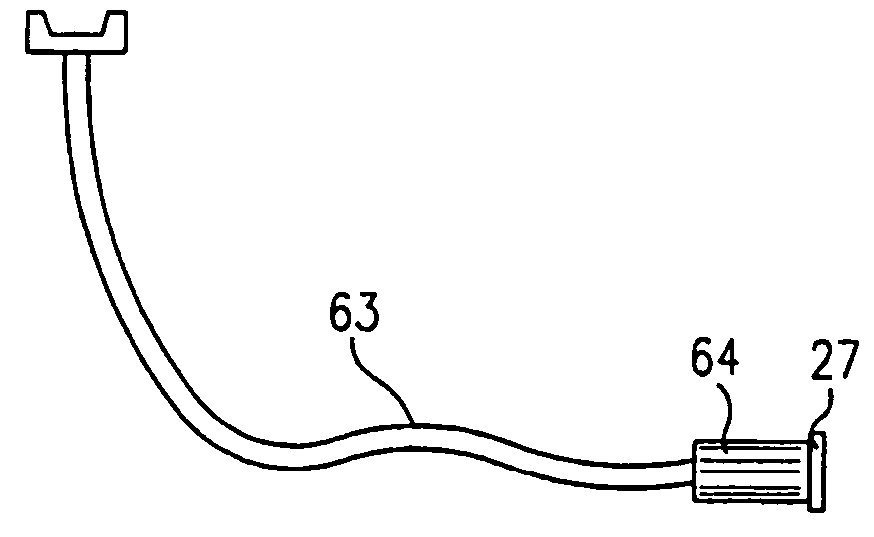
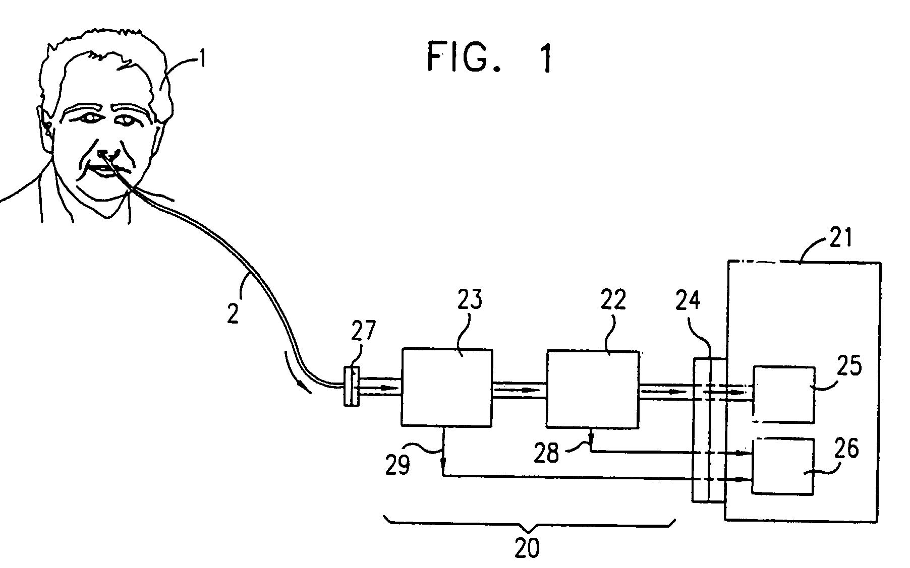
[0069] Reference is now made to FIG. 1, which illustrates schematically a gas analyzer calibration checking device 20, constructed and operative according to a preferred embodiment of the present invention, connected to a breath tester 21. The device consists of two components, the calibration checking unit 22, and the fluid filter unit 23. The subject 1 is connected to the device by means of a disposable nasal or oral sampling tube 2, into which he breathes. This sampling tube is connected to the filter unit 23 of the device by means of a mating connection 27. The sampling tube is preferably of a simple nasal / oral cannula type, such that it is a low cost disposable item.

[0070] The filter unit 23 is attached to the calibration checking unit 22, or is built-into the calibration checking unit, such that the exhaled breath, after any moisture and / or fluids are removed from it, passes through the calibration checking unit 22, into the gas analyzer section 25 of the breath tester 21. Th...


PUM

PropertyMeasurementUnit
volumeaaaaaaaaaa
volumeaaaaaaaaaa
flow rateaaaaaaaaaa

Abstract

A calibration checking device, and methods of mandating its use at regular time intervals, to ensure maintenance of the accuracy of gas analyzers, especially for use with breath tests. Each calibration checking device is designed to be used for a predetermined number of tests. After first connection of a new calibration checking device, a volume of known calibration checking gas is released into the instrument, and a calibration checking measurement is initiated. A signal is sent to a counting mechanism which both enables the use of the instrument, and commences a count of the number of tests performed by the breath tester. When the number of tests is exceeded, the instrument is disenabled. The device can include a moisture filter having an interface with the instrument, which prevents its operation if the filter is used beyond the recommended number of times, or if excess moisture renders it saturated.

Description

FIELD OF THE INVENTION [0001] The present invention relates to the field of gas analyzer calibration and filtering devices, especially for use with breath test instrumentation. BACKGROUND OF THE INVENTION [0002] Gas analyzers are used for many measurement and monitoring functions in science, industry and medicine. In particular, gas spectrometry is becoming widely used in diagnostic instrumentation based on the use of breath tests for detecting a number of medical conditions present in patients. Descriptions of much breath test methodology and instrumentation are disclosed in PCT Publication No. WO99 / 12471, entitled “Breath Test Analyzer” by D. Katzman and E. Carlebach. Methods of constructing and operating gas analyzers such as are used in breath test instrumentation are disclosed in PCT Publication No. WO99 / 14576, entitled “Isotopic Gas Analyzer” by I. Ben-Oren, L. Colman, E. Carlebach, B. Giron and G. Levitsky, some of whom are inventors in the present application. Each of the ab...

Claims


Application Information

Patent Timeline
Patent Type & Authority Applications(United States)
IPC IPC(8): A61BA61B5/08A61B5/083B32B27/04G01N1/22G01N33/497G01N7/00
CPCA61B5/083
Inventor COLMAN, LEWISLEVITSKY, GERSHONBEN-OREN, ILAN
Owner EXALENZ BIOSCIENCE LTD
Why Eureka
Try Eureka