Liquid dispensing device with secondary liquid entrance

a liquid dispensing device and liquid entrance technology, applied in water installations, lavatory sanities, construction, etc., can solve the problems of reducing the production cost of retaining studs, unable to prevent liquid from flowing, and unable to keep the separated part of the seal sealed, etc., to achieve the effect of being convenient to manufactur

Inactive Publication Date: 2005-12-15
WD 40 CO
View PDF6 Cites 23 Cited by
  • Summary
  • Abstract
  • Description
  • Claims
  • Application Information

AI Technical Summary

Benefits of technology

[0021] My invention overcomes the disadvantages of the Leonard retaining stud and does so in a simple and elegant manner, using a structure that is designed to function reliably in all situations and, at the same time, is inexpensive to fabricate. In my structure, a secondary liquid entrance to the liquid conducting member is provided. That entrance is situated in the wall of the liquid conduit such that liquid from the container can always enter the liquid conduit and flow to the dispensing surface, regardless of the state or position of the ruptured part of the container port seal.
[0023] However, in my invention, the extended section of the wall of the conduit member is provided with one or more additional openings which form a secondary liquid entrance to the interior of the conduit. Because of the arcuate shape of the extended section of the conduit wall, and the position of the secondary liquid entrance openings on that extended wall section, those openings cannot be blocked by the broken part of the seal at the same time that the broken part of the seal blocks the open inlet end of the conduit, which constitutes the primary liquid entrance. Thus, either the primary liquid entrance or the secondary liquid entrance of the conduit is always unobstructed. Liquid flow from the container, through the conduit, to the dispensing surface is always assured by this simple structure.

Problems solved by technology

Hence, no liquid would enter the stream of flushed water, defeating the purpose of the liquid dispensing device.
That second projection or stud is designed to retain the separated part of the seal in the open position, such that it cannot move back to a position covering the inlet of the conduit and therefore cannot prevent liquid from flowing from the bottle through the conduit to the dispensing plate surface.
However, the retaining stud may not serve to keep the separated part of the seal from blocking the inlet of the conduit in all situations.
Depending upon the strength of the consumer mounting the bottle on the housing, and the angle at which the conduit is pushed through the seal, the rupture of the seal may not be complete and the inlet to the conduit may remain partially obstructed.
In that case, the seal part may settle down over the conduit inlet, completely or partially obstructing the free flow of liquid through the inlet.

Method used


Image

  • Liquid dispensing device with secondary liquid entrance
  • Liquid dispensing device with secondary liquid entrance
  • Liquid dispensing device with secondary liquid entrance

Examples


Embodiment Construction

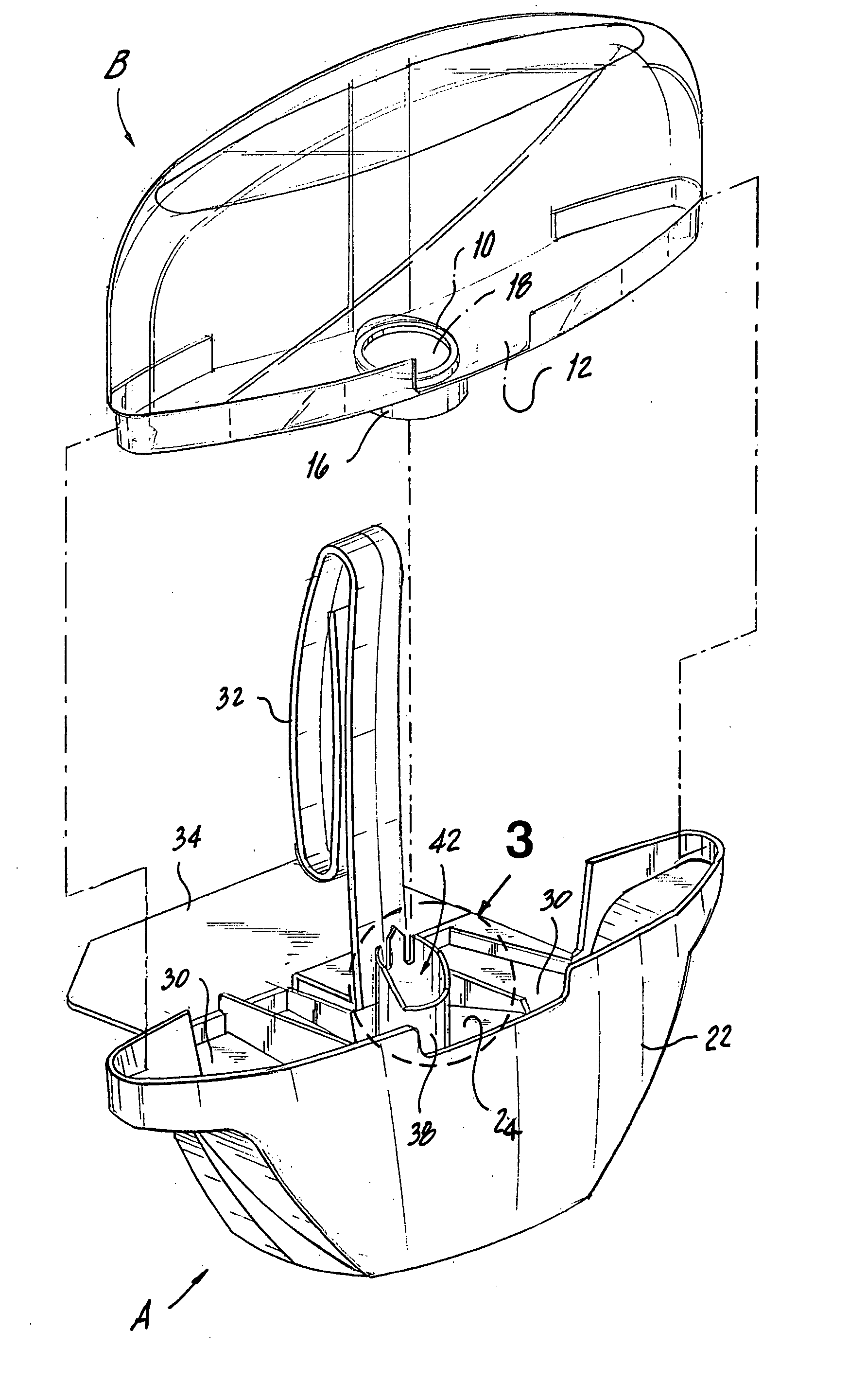
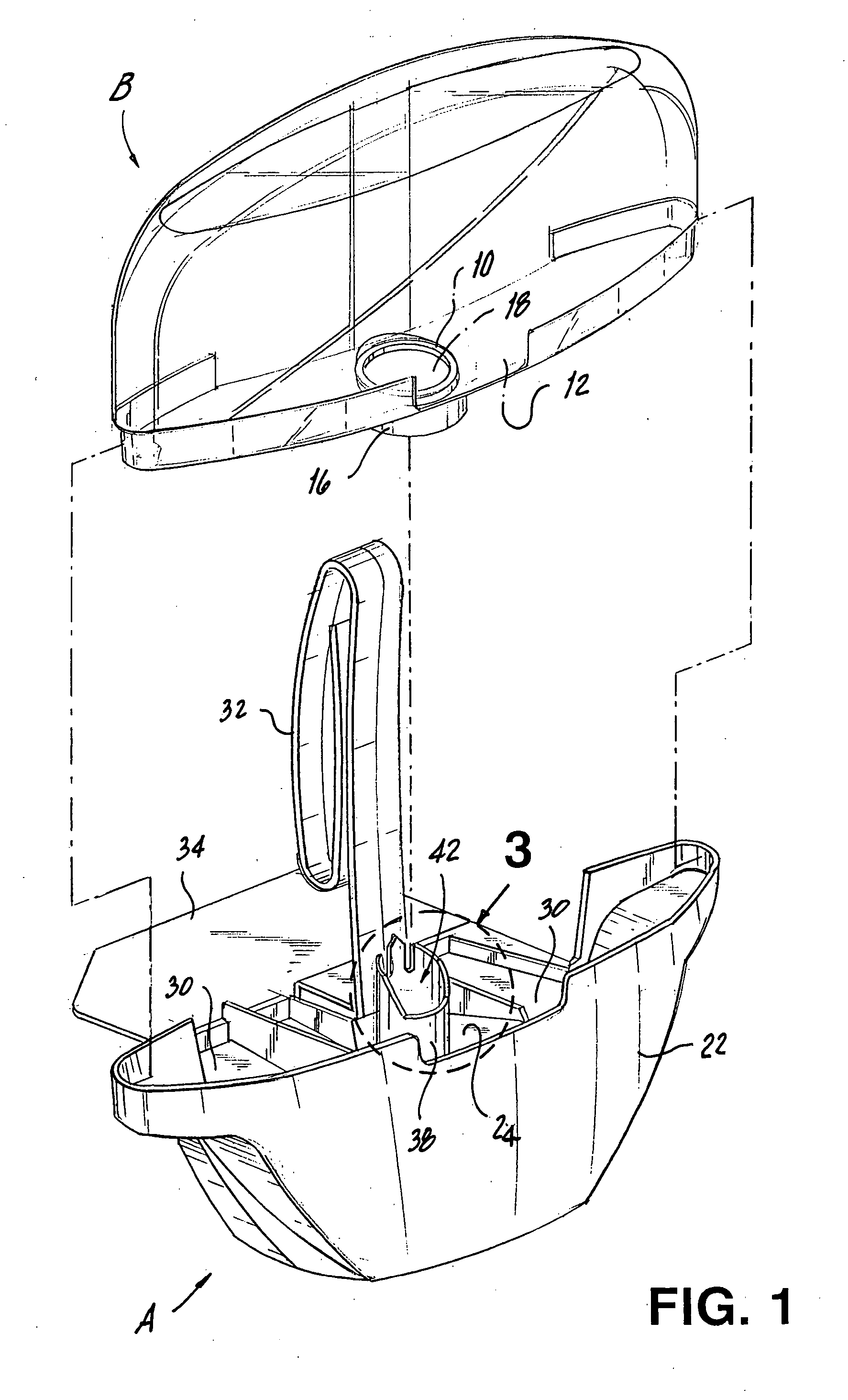
[0059] As seen in FIGS. 1 and 2, the liquid dispensing device of the present invention includes a housing, generally designated A, and a container, generally designated B. Container B is a reservoir for a liquid, that may be a detergent, or other cleaning or deodorizing agent such as bleach, to be dispensed by housing A into the stream of flushed water in the toilet bowl. Although the present invention is particularly useful for dispensing devices designed for dispensing a liquid only, and hence the reference throughout to a liquid container, it should be understood that the present invention is equally applicable in situations where the container has isolated compartments for dispensing a liquid and a solid separately.

[0060] Container B can be of any suitable shape and size and made of any suitable material. However, the container illustrated is generally elongated, to match the generally elongated shape of housing A, has an arcuate top and is fabricated of transparent plastic. Ut...


PUM


Abstract

A device for dispensing liquid from the container to a toilet bowl is provided. The device is used with a liquid container having a normally sealed port. It includes a housing upon which the container is mounted, breaking the seal. The housing has a dispensing surface upon which liquid from the container is deposited and over which at least a portion of the flushed water stream passes. A conduit is provided for conducting liquid from the container to the liquid dispensing surface. The inlet end portion of the conduit has primary liquid entrance means, in the form of an open end, and secondary liquid entrance means, in the form of one or more openings in the conduit wall. The inlet end of the conduit extends through the container port with the open end of the conduit and the openings in the conduit wall both situated within the container. Thus, liquid can enter the channel from the container from either the open end of the conduit or the opening in the conduit wall, regardless of the position of the separated part of the seal.

Description

CROSS-REFERENCE TO RELATED APPLICATIONS [0001] Not Applicable STATEMENT REGARDING FEDERALLY SPONSORED RESEARCH OR DEVELOPMENT [0002] Not Applicable REFERENCE TO A “SEQUENCE LISTING”, A TABLE, OR A COMPUTER PROGRAM LISTING APPENDIX SUBMITTED ON COMPACT DISC [0003] Not Applicable BACKGROUND OF THE INVENTION [0004] 1. Field of the Invention [0005] The present invention relates to an automatic liquid dispensing device of the type used for providing detergent or other liquid from a removable container to the stream of water in a toilet bowl, as the toilet is flushed, and more particularly to such a device in which the seal in the port of the liquid container is broken as it is pushed into the container to open the port, as the container is mounted on the device, by an open ended conduit formed of a cylindrical wall with one or more secondary liquid entrance openings such that liquid from the container can enter the device from the container, even if the open end of the conduit is partial...

Claims


Application Information

Patent Timeline
Patent Type & Authority Applications(United States)
IPC IPC(8): E03D9/02E03D9/03
CPCE03D9/032
Inventor BERNARDUCCI, ERNEST
Owner WD 40 CO
Why Eureka
Try Eureka