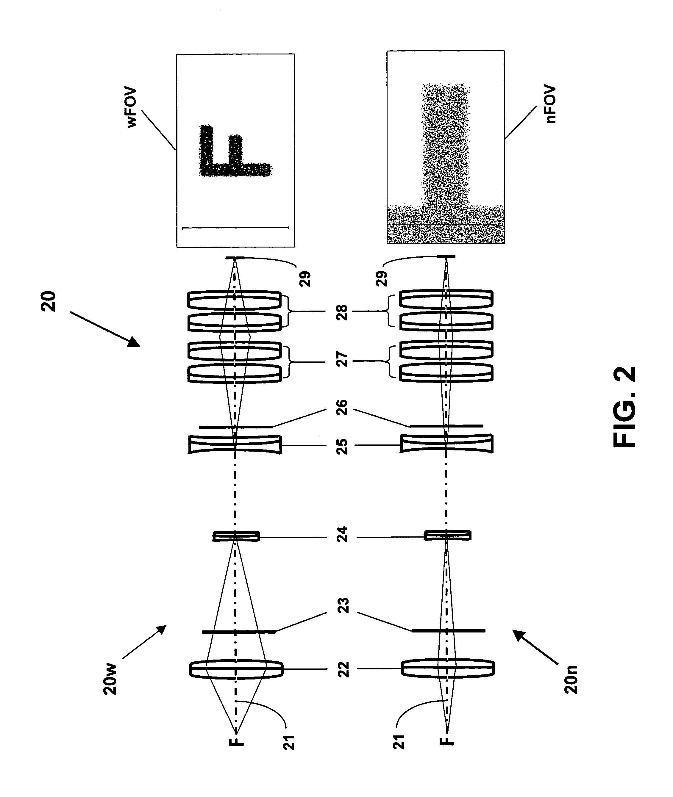
[0013]The key to this concept is to create large changes in system magnification with very small changes in the focal lengths of individual active elements by leveraging the
optical power of conventional, passive optical elements. In particular, the zoom range can be substantially increased by physically separating the active optics from the conventional optics.
Active optics can thereby provide a varying system effective focal length, generating the flexibility in system magnification that is normally accomplished with mechanical motion. Incorporating active optics into a zoom imaging system can completely eliminate the need for cams, gears, pneumatic actuators, or rotating lens elements. The true magnification (i.e., optical zoom) of the imaging system can be varied without gross mechanical motion by adeptly integrating two or more active optical elements into the optical design. By simply readdressing the
voltage scheme that is applied to the active optics, the focal lengths (i.e., defocus) of these adjustable elements, and thus the magnification of the system, can be changed on a
millisecond time scale without macroscopic
moving parts.
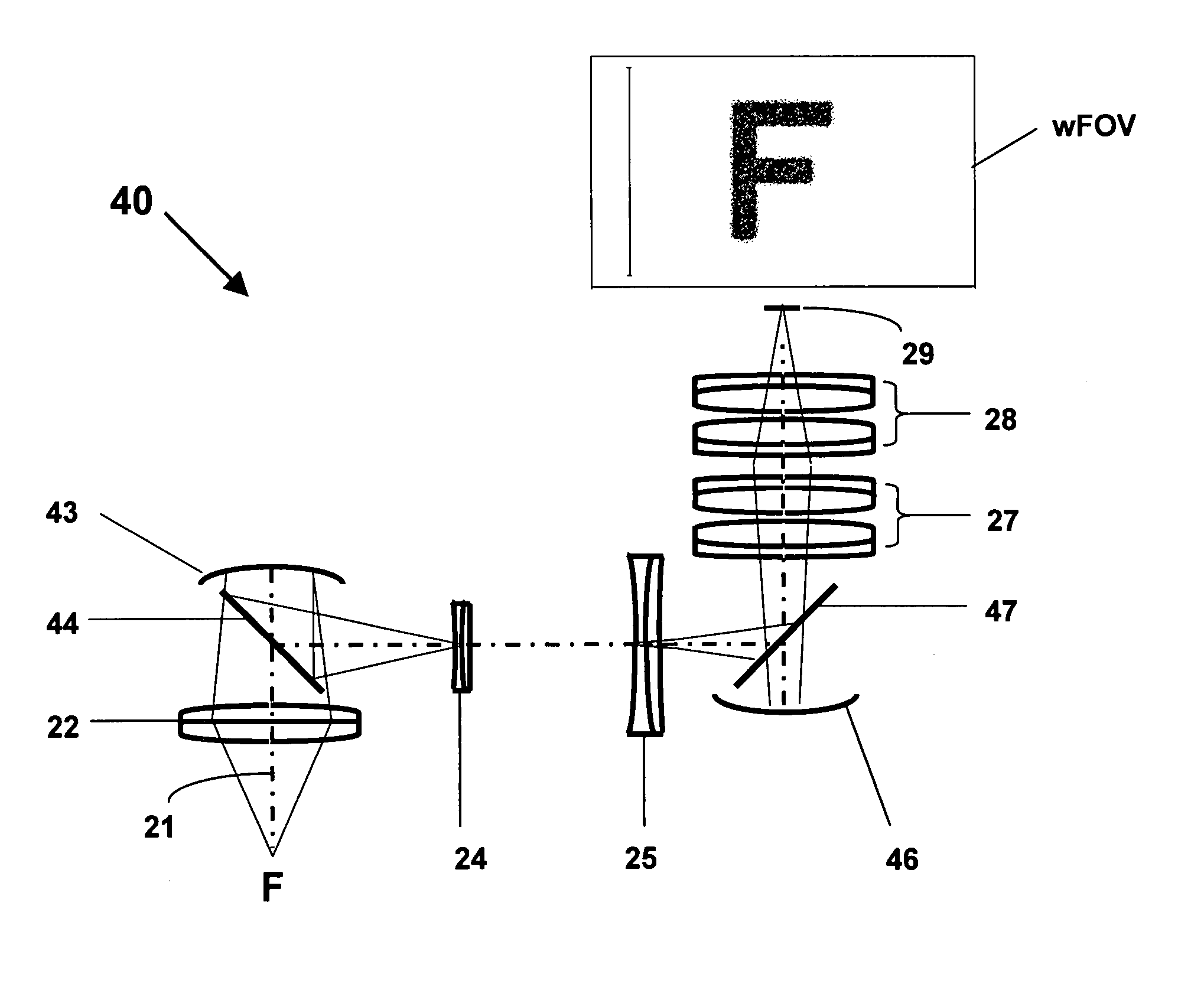
[0014]Additionally, by adding optical tilt along with defocus and smaller amounts of other higher order aberrations to the active optics, optical magnification can be achieved over any area within the wide FOV, not just along the
optical axis as in a conventional system. Thus, the active optical zoom system can, for example, magnify the top right corner of a wide FOV, and by simply adjusting the voltages applied to the active optics, magnify the bottom left corner without moving the imaging system. In particular, this eliminates the need for, or at least reduces the requirements of, gimbals that slew the system to redirect its ‘
gaze’. Thus, replacing moving optics with stationary active optics can significantly enhance the speed and reduce the size, weight, and power requirements of a zoom imaging system. Integrating active optics may also increase system functionality, ruggedness, and
life expectancy, while potentially decreasing overall system cost.
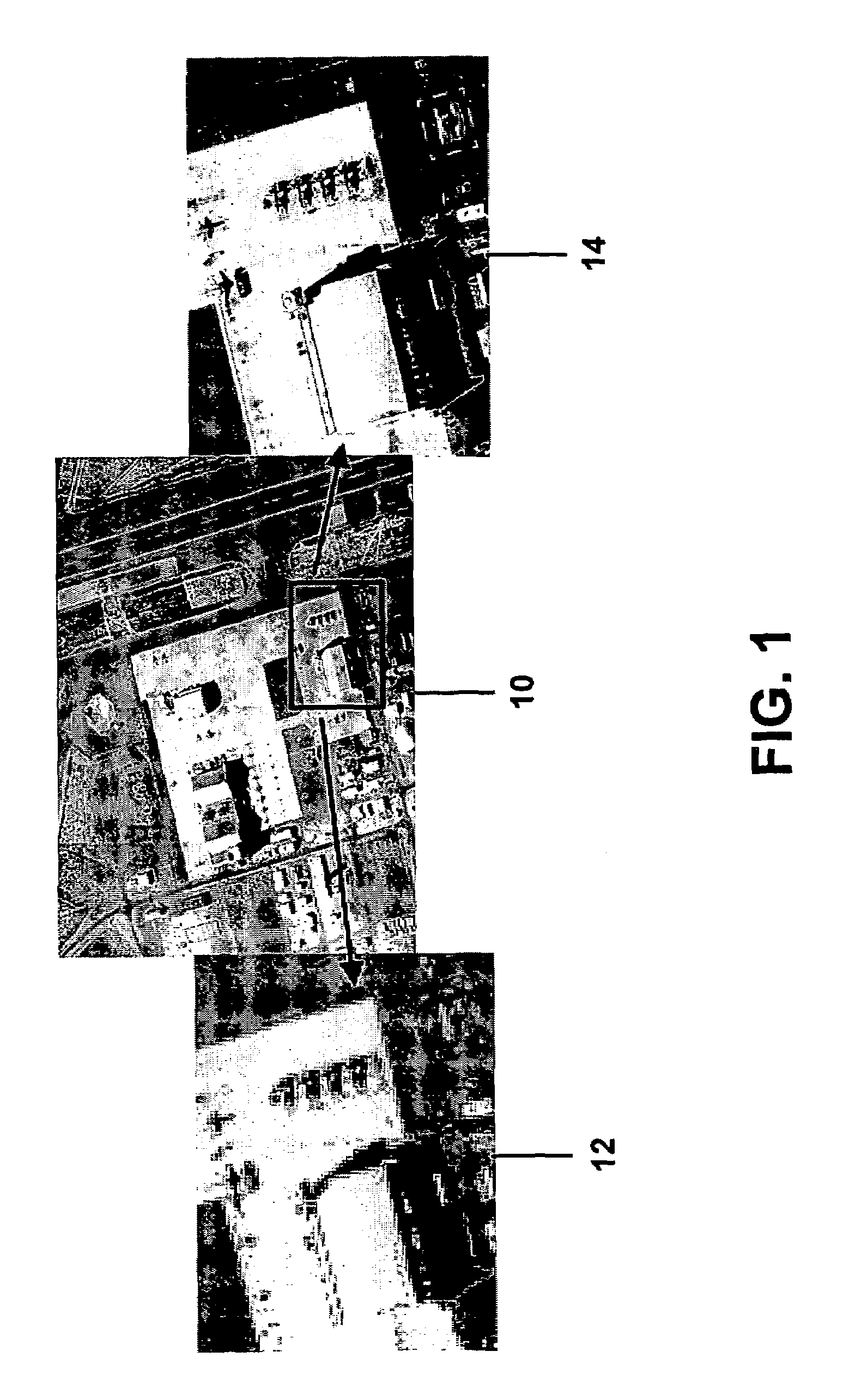
[0015]For example, a reconnaissance
satellite could maintain a wide FOV for surveillance and
threat detection. However, once an area-of-interest is determined, through either operator input or automated
motion detection, an active optical zoom system could nonmechanically zoom-in on that area with increased resolution on a
millisecond time scale for detailed
intelligence gathering or target identification.
High resolution could then be maintained on target without having to slew the optical system, as long as the target object is within the wide FOV of the system. Because the magnification is nonmechanical, multiple objects could be magnified in rapid succession without slewing the optical system. For ATP applications, the system could survey an area for
threat detection, quickly zoom-in on multiple potential targets, and track one /
multiple target(s) in real-time. The system can comprise means to optimize
centroid tracking on the
image plane by utilizing algorithms that
exploit the zoom capability. In other words, the magnification would iteratively adjust to optimize tracking-lock based on the size and power of the tracking spot on the focal plane array. Thus, performance should surpass that of a conventional
tracking system, because of the inherent ability to optimize performance using real-time feedback. By integrating a
feedback loop, errors due to turbulence in the
atmosphere,
satellite jitter, or other dynamic aberrations could simultaneously be removed, similar to the operation of conventional
adaptive optics systems on
astronomical telescopes, significantly improving image fidelity.
[0016]Finally, the use of active optics enables the active optical zoom system of the present invention to correct for other static and dynamic aberrations. For commercial applications that use refractive elements (i.e., lenses), this allows for the use of cheaper, light-weight plastic lenses, which are of lower
optical quality than glass lenses. For a
reflective system, replicated or composite mirrors, which are lighter weight and cheaper to fabricate, can be used instead of higher
optical quality polished glass mirrors. The active optics, already in the system for zooming, can be used to remove any residual aberrations, giving identical, or improved, imaging performance as can be obtained with the more expensive and heavier glass lenses or mirrors. Similarly, the active optics can also provide correction of aberrations that are inherent to a system, such as those created by imaging through the nosecone of a
projectile. In addition, the active optics can be used to correct dynamic aberrations, such as those caused by turbulence in the
atmosphere. By integrating a
wavefront sensor with a control loop in an imaging system, dynamic aberrations can be removed at kHz rates, similar to what is currently done on
astronomical telescopes using adaptive optical mirrors.

