Method for measuring localized corrosion rate with a multi-electrode array sensor

a multi-electrode array and sensor technology, applied in the direction of liquid/fluent solid measurement, material electrochemical variables, instruments, etc., can solve the problems of not being able to accurately detect corrosion rate and local corrosion of anodic sites

Active Publication Date: 2005-12-15
SOUTHWEST RES INST
View PDF14 Cites 17 Cited by
  • Summary
  • Abstract
  • Description
  • Claims
  • Application Information

AI Technical Summary

Problems solved by technology

When these sites are far apart, the anodic sites corrode locally.
In general, the overall current

Method used


Image

  • Method for measuring localized corrosion rate with a multi-electrode array sensor
  • Method for measuring localized corrosion rate with a multi-electrode array sensor
  • Method for measuring localized corrosion rate with a multi-electrode array sensor

Examples


Embodiment Construction

[0014] Overview

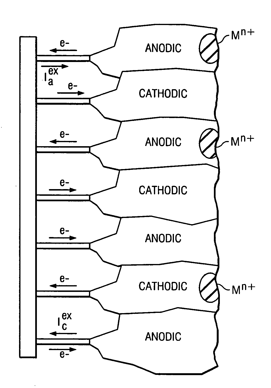
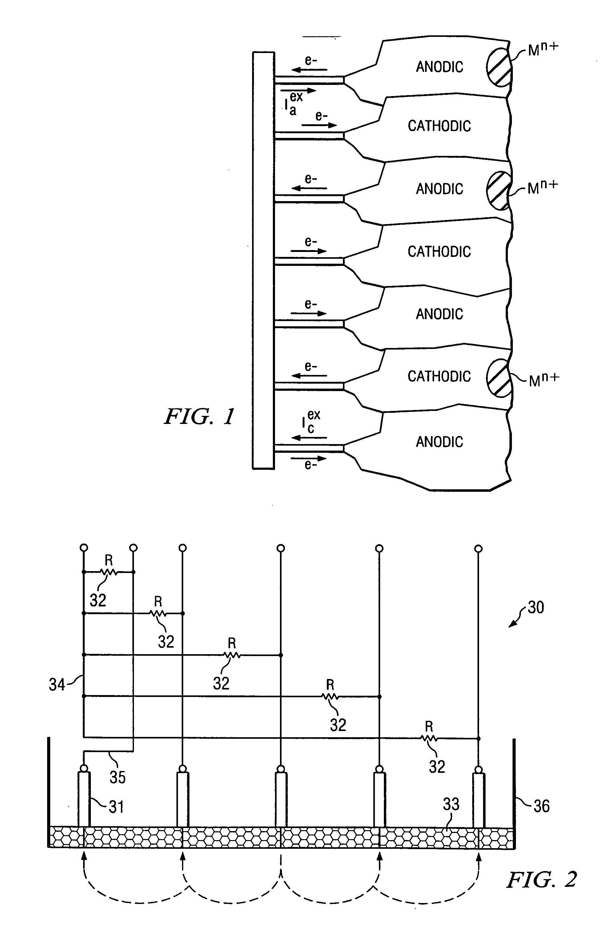
[0015] As stated in the Background, U.S. Pat. No. 6,132,593 and U.S. Pat. No. 6,683,463 each describe types of multi-electrode array sensors for monitoring localized corrosion. In particular, the latter array has been tested extensively using carbon steels, stainless steels, and nickel-base alloys as probe elements in cooling bacteria, under salt deposits, concentrated chloride solutions, and a process stream of a chemical plants. It has been demonstrated that the sensor is highly sensitive to the corrosiveness of the environments for localized corrosion.

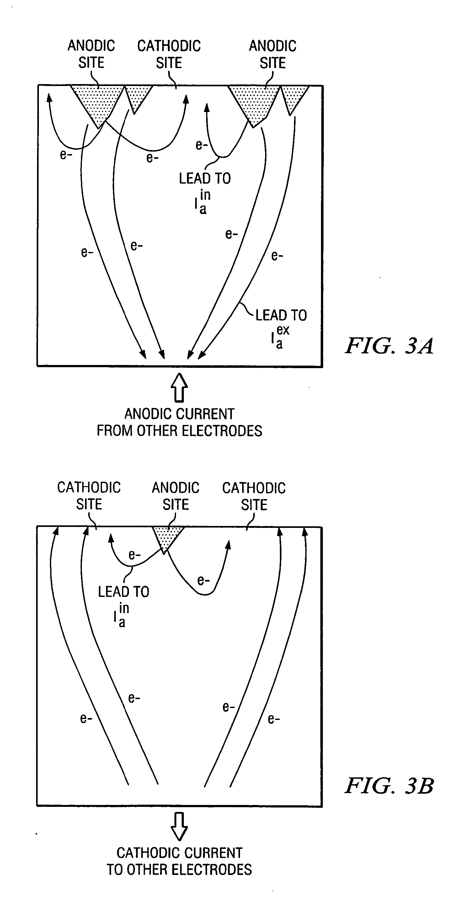
[0016] Quantitative prediction of the penetration rate of localized corrosion involves the assumption that there is no current that flows internally on the most corroded electrode. This assumption may be true or close to reality if the environment is highly corrosive and some of the sensor electrodes are severely corroded. However, for a less corrosive environment, or during the early stages of corrosion when no ele...


PUM


Abstract

A method of measuring localized corrosion, using a multi-electrode array sensor. The method eliminates the effect of internal current in corroded electrodes, and thus provides a more accurate corrosion measurement. In one embodiment, the potential of a common node of the sensor is adjusted so that the sensor's most cathodic current is close to zero.

Description

RELATED PATENT APPLICATION [0001] This application claims the benefit of U.S. Provisional Application No. 60 / 560,858, filed Apr. 9, 2004 by Lietai Yang and entitled “Improved Method for Measuring Localized Corrosion Rate with a Multi-Electrode Array Sensor”.TECHNICAL FIELD OF THE INVENTION [0002] This invention relates to methods for detecting corrosion in metals, and more particularly methods for using a sensor having an array of electrochemical cells. BACKGROUND OF THE INVENTION [0003] Corrosion is a natural process that involves a metal atom M being oxidized, whereby it loses one or more electrons and leaves the bulk metal, M−>Mm++m e−. The lost electrons are conducted through the bulk metal to another site where they reduce (i.e. combine with) a reducible species such as a dissolved gas or a positively charged ion G+ that is in contact with the bulk metal, N+n e−−>Nn− and Gm++m e−−>G. [0004] In corrosion parlance, the site where metal atoms lose electrons is called the ...

Claims


Application Information

Patent Timeline
IPC IPC(8): G01N17/02G01N27/26G01N27/403
CPCG01N17/02
Inventor YANG, LIETAI
Owner SOUTHWEST RES INST
Why Eureka
Try Eureka