

Fuel injector with multi-part injection valve member and with pressure booster
a fuel injector and multi-part technology, which is applied in the direction of fuel injection apparatus, machine/engine, feed system, etc., can solve the problems of limited improvement in the fill level attainable, and achieve the effects of short trigger time, high hydraulic flow rate, and short injection duration
- Summary
- Abstract
- Description
- Claims
- Application Information
AI Technical Summary
Benefits of technology
Problems solved by technology
Method used
Image

Examples
Embodiment Construction
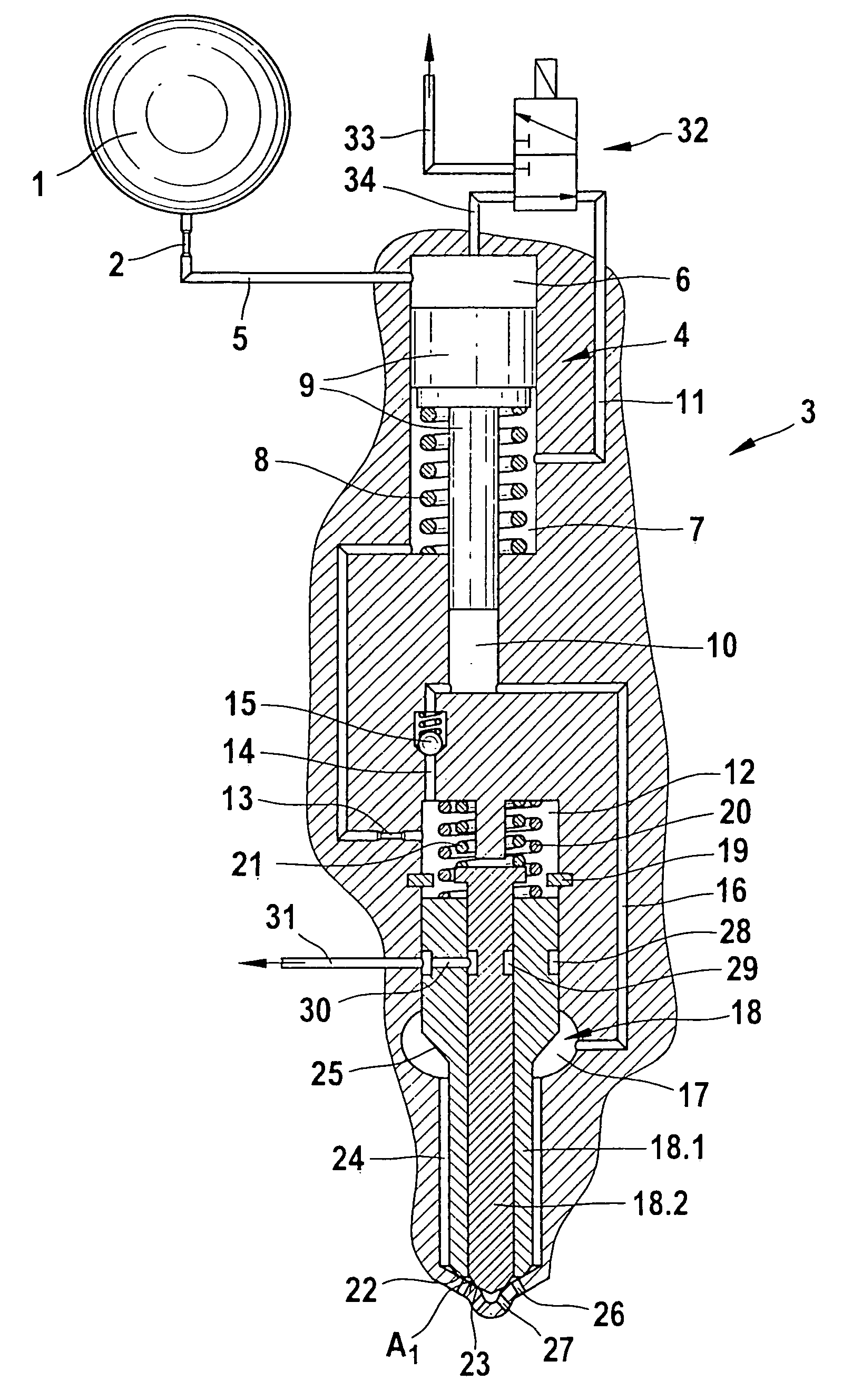
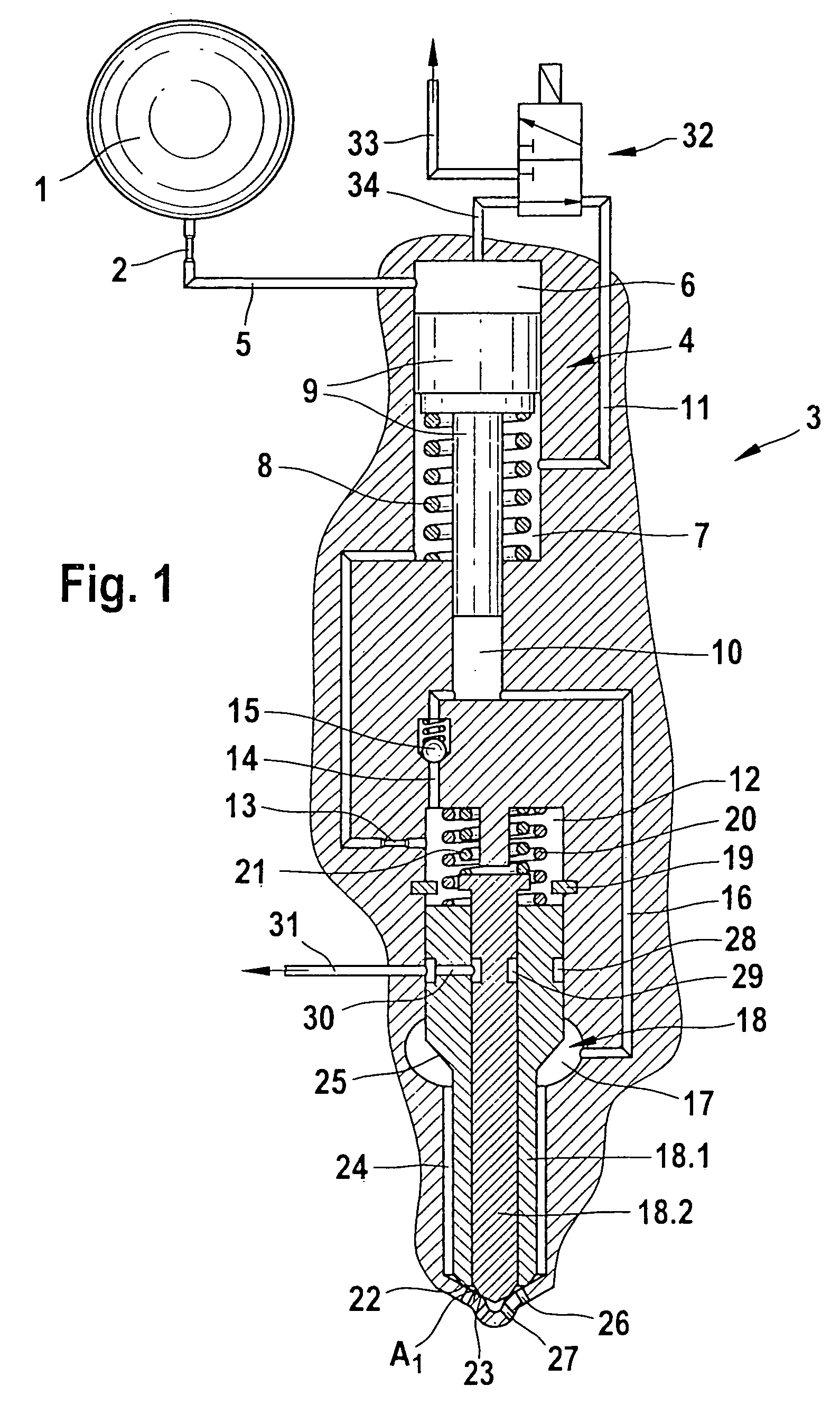
[0018] A prior art fuel injector 3 shown in FIG. 1 is supplied with fuel that is at high pressure via a high-pressure reservoir 1 (common rail). The high-pressure reservoir 1 is supplied with fuel via a high-pressure pump, which compresses the fuel and delivers it to the high-pressure reservoir 1. The fuel pressure prevailing in the high-pressure reservoir 1 (common rail) is thus available at each fuel injector 3 of the internal combustion engine. The fuel injector 3 includes a control valve 32, a pressure booster 4, and an injection valve member 18 which may be embodied in multiple parts.
[0019] The pressure booster 4 is embodied as an axially displaceable stepped piston 9; the stepped piston 9 divides a work chamber 6, which is acted upon via a high-pressure line 5, from a pressure-relievable differential pressure chamber 7. The stepped piston 9 is acted upon via a restoring spring 8, which moves the stepped piston 9 into its upper position. Upon pressure relief of the differentia...
PUM
 Abstract
Description
Claims
Application Information