Oxygenating nozzle

a technology of oxygenating nozzles and nozzles, which is applied in the direction of sustainable biological treatment, biological water/sewage treatment, separation processes, etc., can solve the problems of limiting the installation amount of water, the nozzles used today are not able to give a sufficient level of dissolved oxygen, and the capacity is relatively small

Active Publication Date: 2005-12-15
MESSER IND USA INC
View PDF15 Cites 12 Cited by
  • Summary
  • Abstract
  • Description
  • Claims
  • Application Information

AI Technical Summary

Benefits of technology

[0003] At hatcheries it is important that the content of dissolved oxygen in the water is kept high. Nozzles used today are not able to give a sufficient level of dissolved oxygen. Because the solubility of gases in water is reduced by increasing the temperature while the oxygen need of the fish is increasing at high temperatures, there is a particularly great need for oxygen in warm periods. Increasing the capacity of oxygen dissolvers is therefore highly useful for the fish farmer. In addition, most of the fish hatcheries produce more fish per litre water than the installation originally was dimensioned for. The amount of water is therefore a limiting factor of the installation. A better utilisation of the water, a higher consumption of the oxygen and an improved dissolving capacity are therefore required.
[0004] Most hatcheries use pressurised oxygen dissolvers with a working pressure of 1-4 bars. By small amounts of water, it is normal to let all of the water flow go through the dissolver, but most commonly there is an outlet leading a part of the flow from the main pipe to a booster pump which pressurises the dissolver. The oxygenated water is thereafter led back to the main pipe where it is mixed with untreated water. Most dissolving systems have an efficiency close to 100% using approximately 1.8-2.0 kWH per kilo O2 at maximum dose, dependent upon the choice of pump. Injectors in combination with pressurised O2 dissolvers are not common in Norway. The injectors which have been used have given a relatively small increase in the capacity, a great loss of pressure, and increased consumption of energy.
[0005] U.S. Pat. No. 5,935,490 describes an apparatus for dissolving a gas into a fluid stream. The apparatus has an annular body disposed to define a throttle in the fluid stream. The body has a plurality of inwardly facing apertures in communication with a supply of pressurised gas. Each of the apertures defines a localised injection point for the pressurised gas into the fluid stream. The annular body has a progressively reduced cross-sectional area, such that the resultant velocity and pressure differentials enhance dissolution of gas in the fluid.
[0008] According to the present invention, the nozzle noses point downwards in the direction of the flow and the nozzle noses cover the gas supplying apertures. This reduces the danger of clogging the apertures due to impurities in the water. Each nozzle encircles the cross sectional area and will therefore give a larger area for gas supply. The larger area for gas supply causes the gas pressure and water pressure at the point of supply to be approximately equal, and this and the pointed nozzles cause very few gas bubbles to be generated. Small bubbles have a large surface relative to mass and will therefore give a relatively rapid mass transportation from gas to liquid. SUMMARY OF THE INVENTION

Problems solved by technology

Nozzles used today are not able to give a sufficient level of dissolved oxygen.
The amount of water is therefore a limiting factor of the installation.
The injectors which have been used have given a relatively small increase in the capacity, a great loss of pressure, and increased consumption of energy.
Impurities in the water can cause clogging of the canals for the gas supply, especially when supplying small amounts of gas or at a low gas pressure.
At upstream and horizontal installations, the pressure difference will be considerable and results in the gas emanating mainly through the canals at the smallest cross-sectional area.

Method used


Image

  • Oxygenating nozzle
  • Oxygenating nozzle
  • Oxygenating nozzle

Examples


example

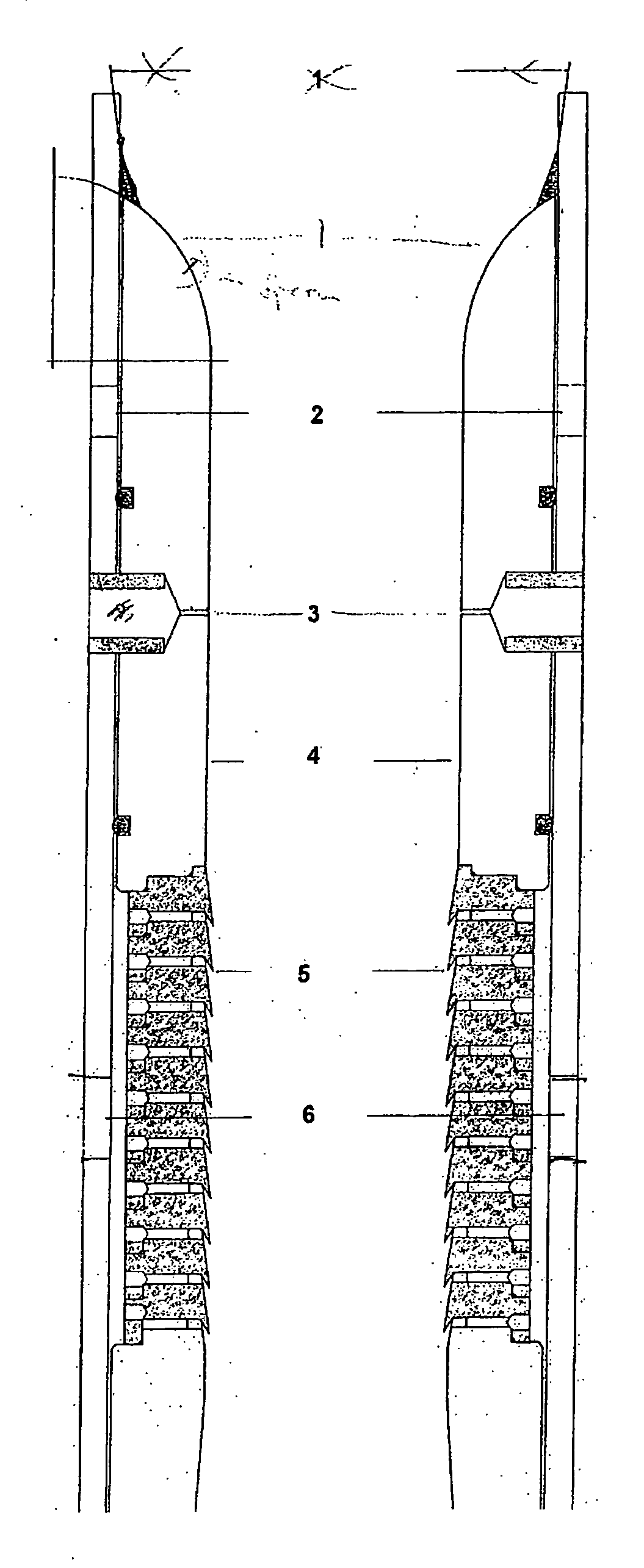
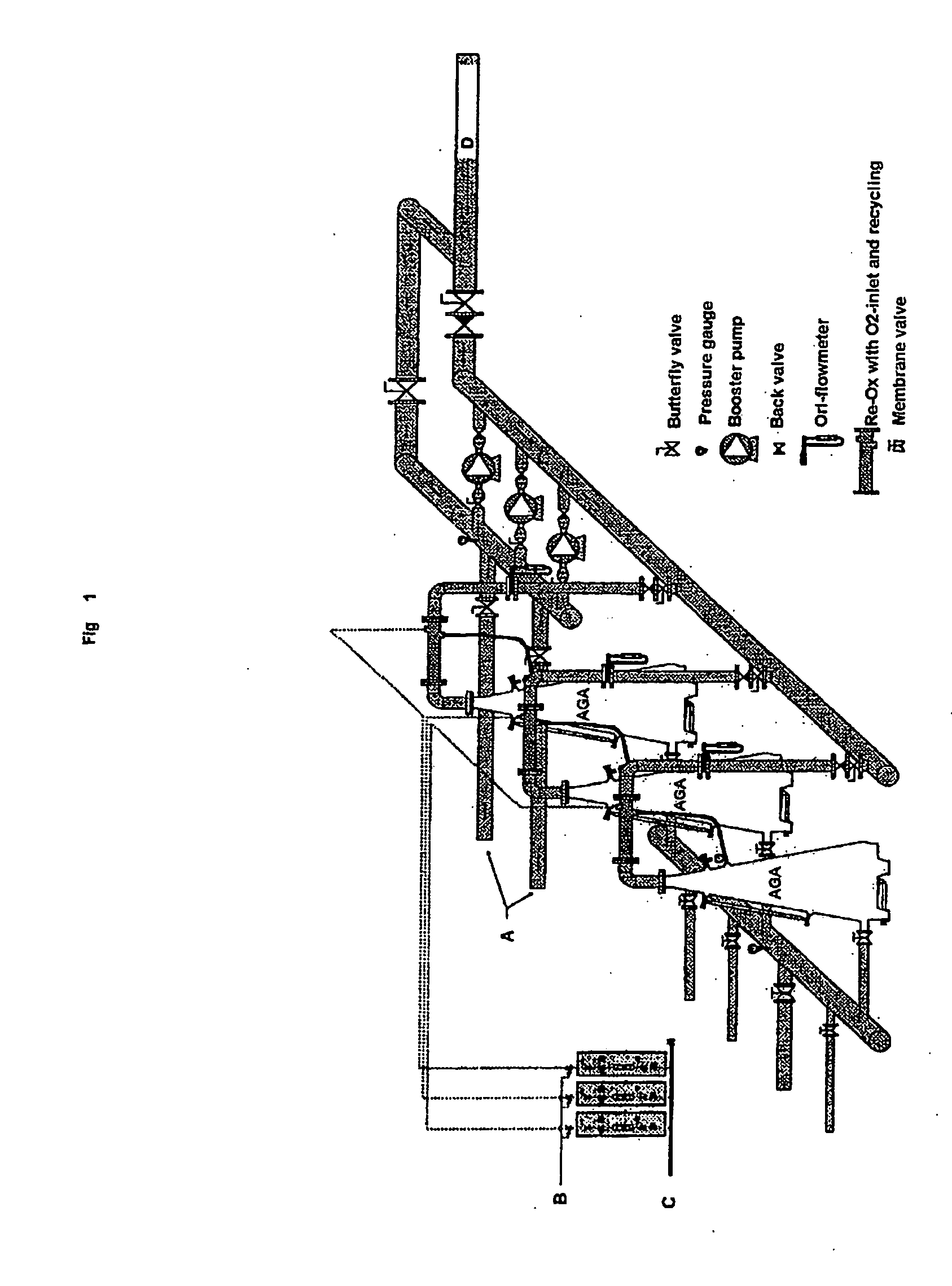
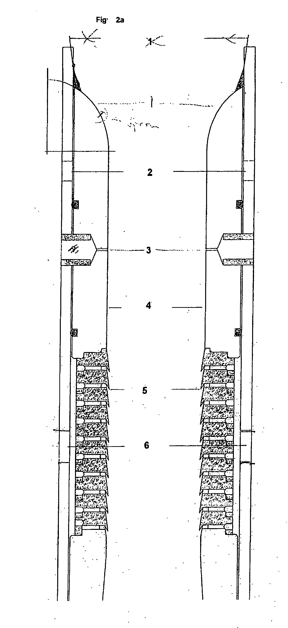
[0027] The technique behind the nozzle arrangement is to utilize pressure differences to recycle gas from the gas volume on top of the cone back into the inlet water which is reentering the cone. On the basis of a cone having a capacity of 60 m3 / h water, 3.8 bar pressure and temperature of 10° C. there can be dosed an amount of 6.25 kg / h oxygen. Tests have been done at the AGA test centre on the cone with a flow rate and pressure as described. The tests show that the use of the nozzle arrangement according to the invention increases the capacity of the cone with up to 9.7 kg, i.e. a 50% increase, which gives a capacity of about 78% of theoretical capacity. A hatchery which has to increase their oxygenating capacity from 2 to 3 cones can choose to install the present invention on their cones and thereby obtain the same total capacity. In addition, the energy consumption per kilo dissolved oxygen is substantially reduced.


PUM

PropertyMeasurementUnit
angleaaaaaaaaaa
angleaaaaaaaaaa
angleaaaaaaaaaa

Abstract

The present invention relates to a nozzle unit for the supply of gas into a liquid comprising two or more annular nozzles one after the other in the direction of flow. The nozzles are angled to give a restriction in the direction of flow, and each nozzle overlaps the following nozzle. Each nozzle has one or more apertures for the supply of gas at the overlap.

Description

[0001] The present invention relates to a nozzle element for the injection of gas into a liquid. [0002] The present invention is an arrangement for increasing the capacity for dissolving a gas in a liquid, for example for dissolving of oxygen in water in an oxygenation cone under pressure. The pressurised oxygenation cone can for example be mounted in a fish hatchery. [0003] At hatcheries it is important that the content of dissolved oxygen in the water is kept high. Nozzles used today are not able to give a sufficient level of dissolved oxygen. Because the solubility of gases in water is reduced by increasing the temperature while the oxygen need of the fish is increasing at high temperatures, there is a particularly great need for oxygen in warm periods. Increasing the capacity of oxygen dissolvers is therefore highly useful for the fish farmer. In addition, most of the fish hatcheries produce more fish per litre water than the installation originally was dimensioned for. The amou...

Claims


Application Information

Patent Timeline
Patent Type & Authority Applications(United States)
IPC IPC(8): B01F5/04B01F3/04
CPCA01K63/042B01F3/0446B01F5/0418B01F5/0423B01F5/0428B01F5/0475B01F5/0485B01F2003/04879C02F3/1294Y10S261/75Y02W10/15Y02W10/10B01F23/232B01F23/237612B01F25/3123B01F25/31233B01F25/31242B01F25/3142B01F25/31425B01F23/2326
Inventor GLOMSET, KARSTEN
Owner MESSER IND USA INC
Why Eureka
Try Eureka