Plate and gasket for a plate heat exchanger

a technology of heat exchanger and plate, which is applied in indirect heat exchangers, laminated elements, light and heating apparatus, etc., can solve the problems of reducing the potential heat exchange area and the design of the clamping means is rather complicated, so as to improve the heat exchanger and achieve the effect of optimum utilisation of the plate, improved heat exchanger and improved sealing

Active Publication Date: 2011-10-27
ALFA LAVAL CORP AB
View PDF7 Cites 9 Cited by
  • Summary
  • Abstract
  • Description
  • Claims
  • Application Information

AI Technical Summary

Benefits of technology

[0007]The object of the invention is to provide an improved heat exchanger plate and to prevent or at least reduce the disadvantages indicated above and to provide a better solution for a heat exchanger plate which comprises a gasket and a gasket groove. Particular aims are a new and better heat exchanger plate and a gasket which enables optimum utilisation of the plate's heat transfer region and thereby results in better plate heat exchanger performance with a given number of plates.
[0009]The invention makes it possible to provide a heat exchanger plate where a larger proportion of the plate's surface can be utilised for heat transfer.
[0018]The invention makes it possible to produce a heat exchanger of increased performance. The number of plates can be reduced while maintaining the same capacity, resulting in cost savings on both material and space. Since many applications, e.g. those for aggressive media, involve very expensive material, the heat transfer capacity and hence the number of heat exchanger plates are of crucial cost significance. It is not unusual for a plate heat exchanger to comprise up to a thousand heat exchanger plates, which means that even a seemingly slight capacity improvement of a heat exchanger plate and a plate heat exchanger according to the invention may have a very large impact on profitability.

Problems solved by technology

The drawbacks with the above solutions are that they require a lot area along the heat exchanger plate edges to be applied and thereby the potential heat exchange area is reduced.
Further the design of the clamping means is rather complicated.

Method used


Image

  • Plate and gasket for a plate heat exchanger
  • Plate and gasket for a plate heat exchanger
  • Plate and gasket for a plate heat exchanger

Examples


Embodiment Construction

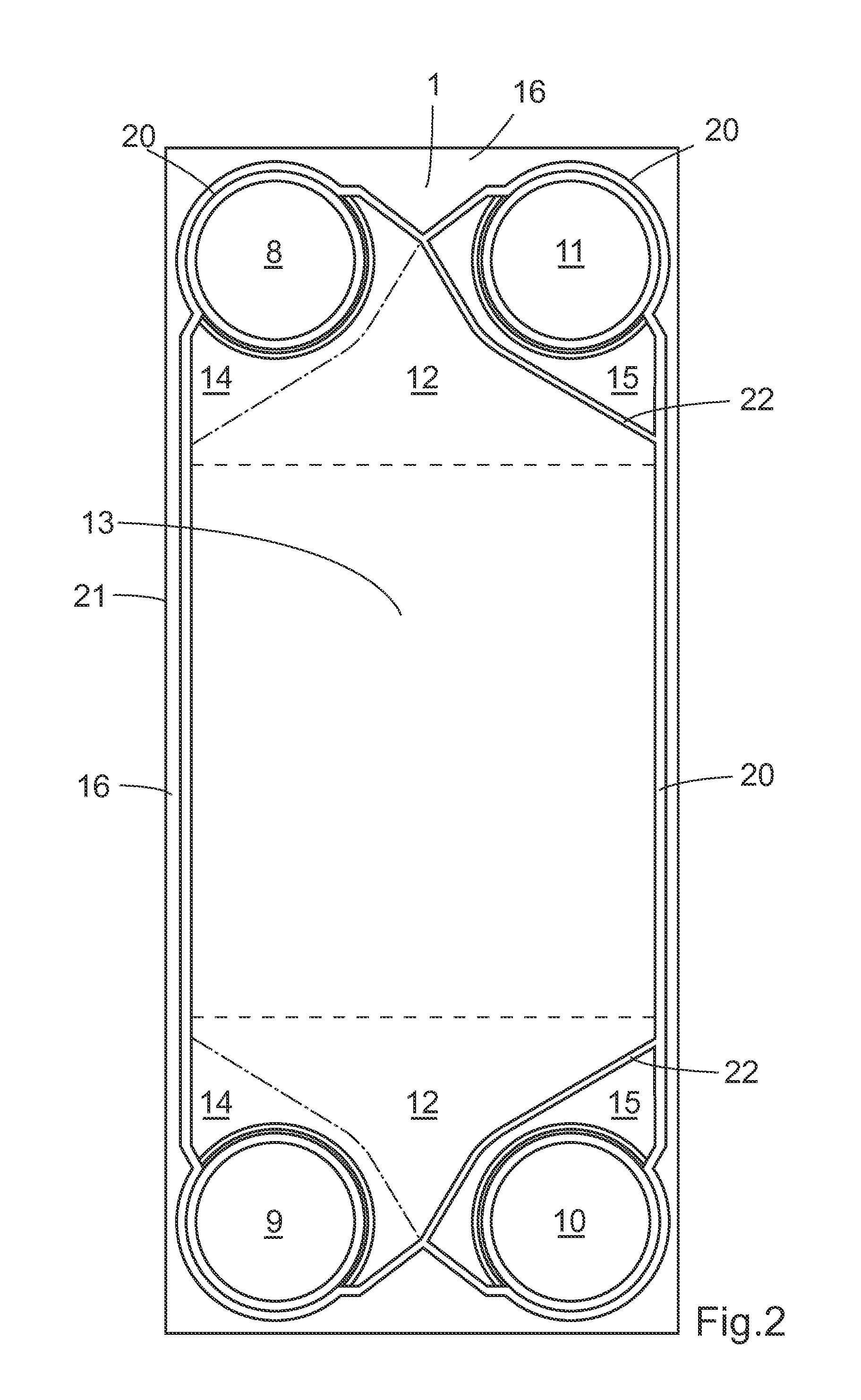
[0027]Heat exchangers are used for transferring heat between two fluids separated by a solid body. Heat exchangers can be of several types, the most common are spiral heat exchangers, tubular heat exchangers and plate heat exchangers. Plate heat exchangers are used for transferring heat between a hot and a cold fluid that are flowing in alternate flow passages formed between a set of heat exchanger plates. The arrangement of heat exchanger plates defined above is enclosed between end plates that are relatively thicker than the heat exchanger plates. The inner surface of each end plate faces the heat transfer plates.

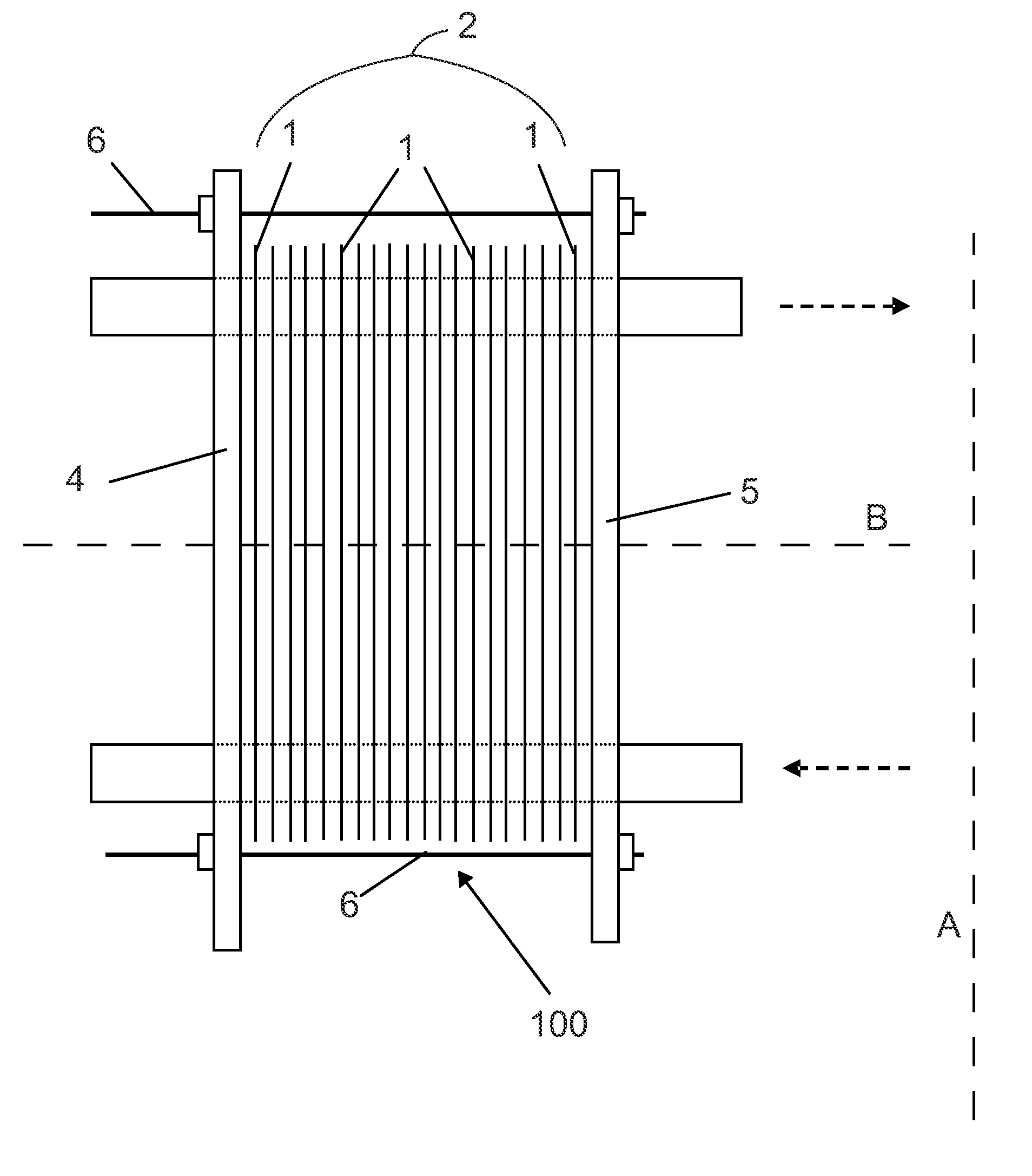
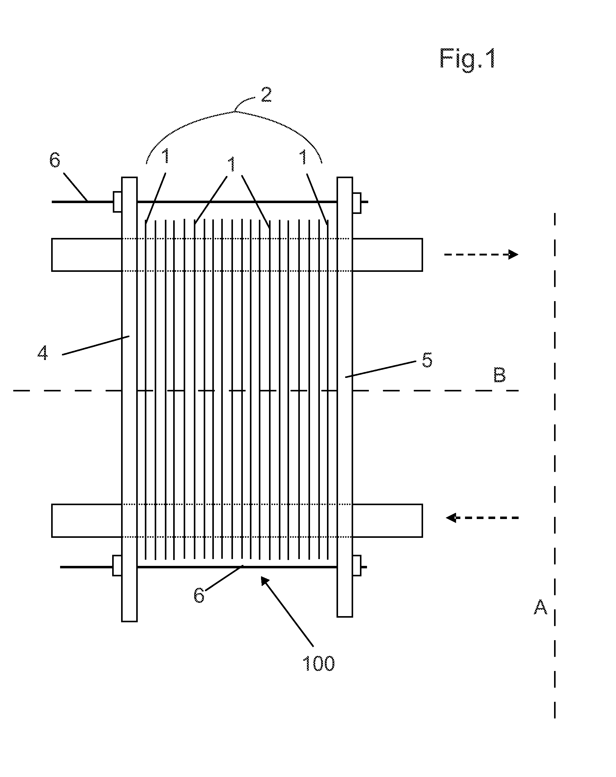
[0028]FIG. 1 discloses a schematic view of a plate heat exchanger 100 comprising a number of compression-molded heat exchanger plates 1, which heat exchanger plates 1 are provided in parallel to each other and successively in such a way that they form a plate package 2. The plate package 2 is provided between a first end plate 4, also called frame plate, and a second end ...


PUM


Abstract

The invention relates to a heat exchanger plate for a plate heat exchanger, whereby the heat exchanger plate has a number of ports, distribution regions, adiabatic regions, a heat transfer region, and an edge region which extends outside the ports and the regions, whereby the heat exchanger plate includes a gasket groove extending in the edge region outside the regions and round the ports, whereby the gasket groove accommodates a gasket for sealing abutment against an adjacent heat exchanger plate in the plate heat exchanger where the gasket groove creates at least a recess of the heat transfer region along each side of the heat transfer region and that the recess enables a clip-on tab to be securely fastened to an edge region of the heat exchanger plate at the recess.

Description

AREA OF INVENTION[0001]The present invention refers generally to plate heat exchangers allowing a heat transfer between two fluids at different temperature for various purposes. Specifically, the invention relates to a heat exchanger plate and to a gasket for the heat exchanger plate and a plate heat exchanger comprising the heat exchanger plate and the gasket according to the invention.BACKGROUND OF INVENTION[0002]Plate heat exchangers provided with gaskets normally comprise a plate package of heat exchanger plates disposed adjacent to one another. Gaskets are disposed between the heat exchanger plates. The plate package may also formed by heat exchanger plates that are permanently joined together in pairs to form so-called cassettes, e.g. by welding or brazing, with gaskets placed between the respective cassettes. The gaskets are accommodated in gasket grooves formed during the form-pressing of the heat exchanger plates. Plate heat exchangers further comprise inlet and outlet port...

Claims


Application Information

Patent Timeline
Patent Type & Authority Applications(United States)
IPC IPC(8): F28F3/12
CPCF28F3/046F28F2275/085F28F3/10F28F3/083F28D9/00F28F3/02F28F3/08F28D9/005
Inventor KRANTZ, JOAKIM
Owner ALFA LAVAL CORP AB
Why Eureka
Try Eureka