
Method, system and mould-box for creating form-moulded items of edible ice

a technology of edible ice and mouldbox, which is applied in the field of method, system and mouldbox for creating formmoulded items of edible ice, can solve the problems of not being edible-item friendly not being able to meet the needs of edible items,

Active Publication Date: 2006-02-16
TETRA LAVAL HLDG & FINANCE SA
View PDF13 Cites 9 Cited by
  • Summary
  • Abstract
  • Description
  • Claims
  • Application Information

AI Technical Summary

Benefits of technology

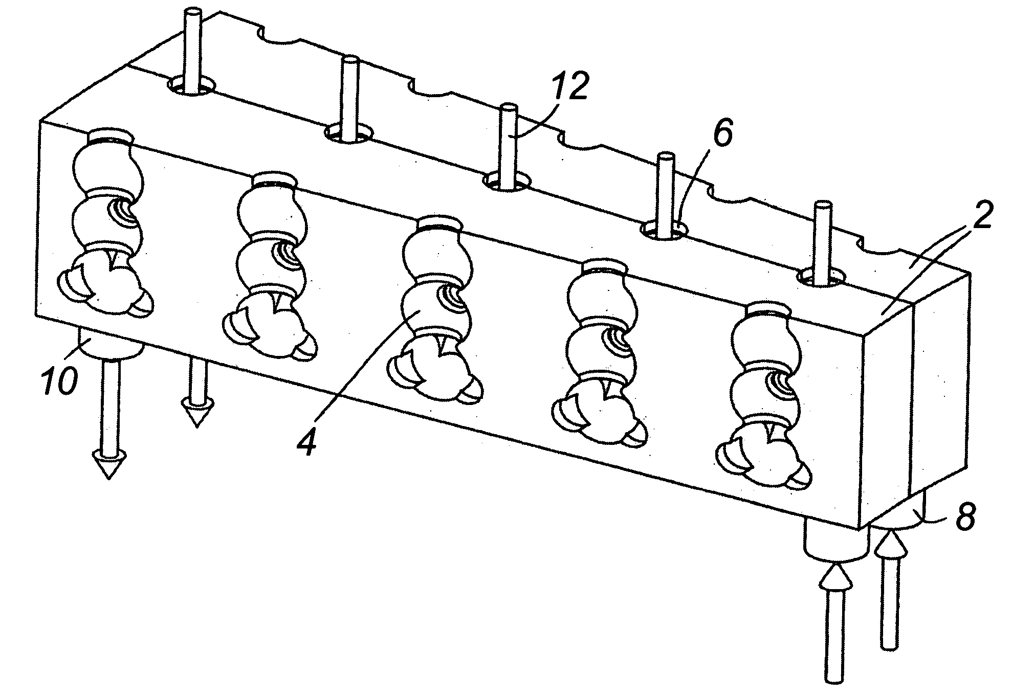
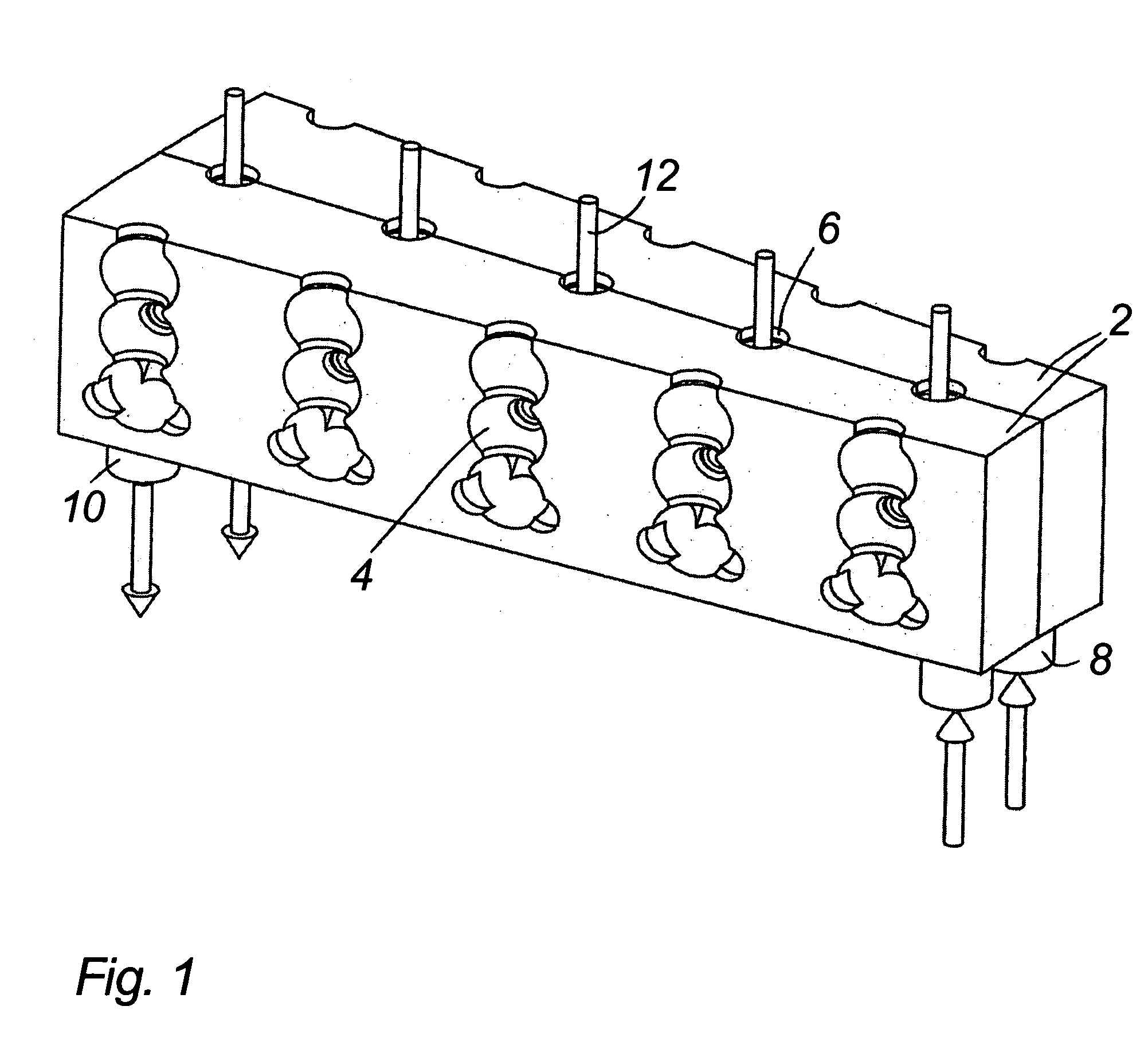
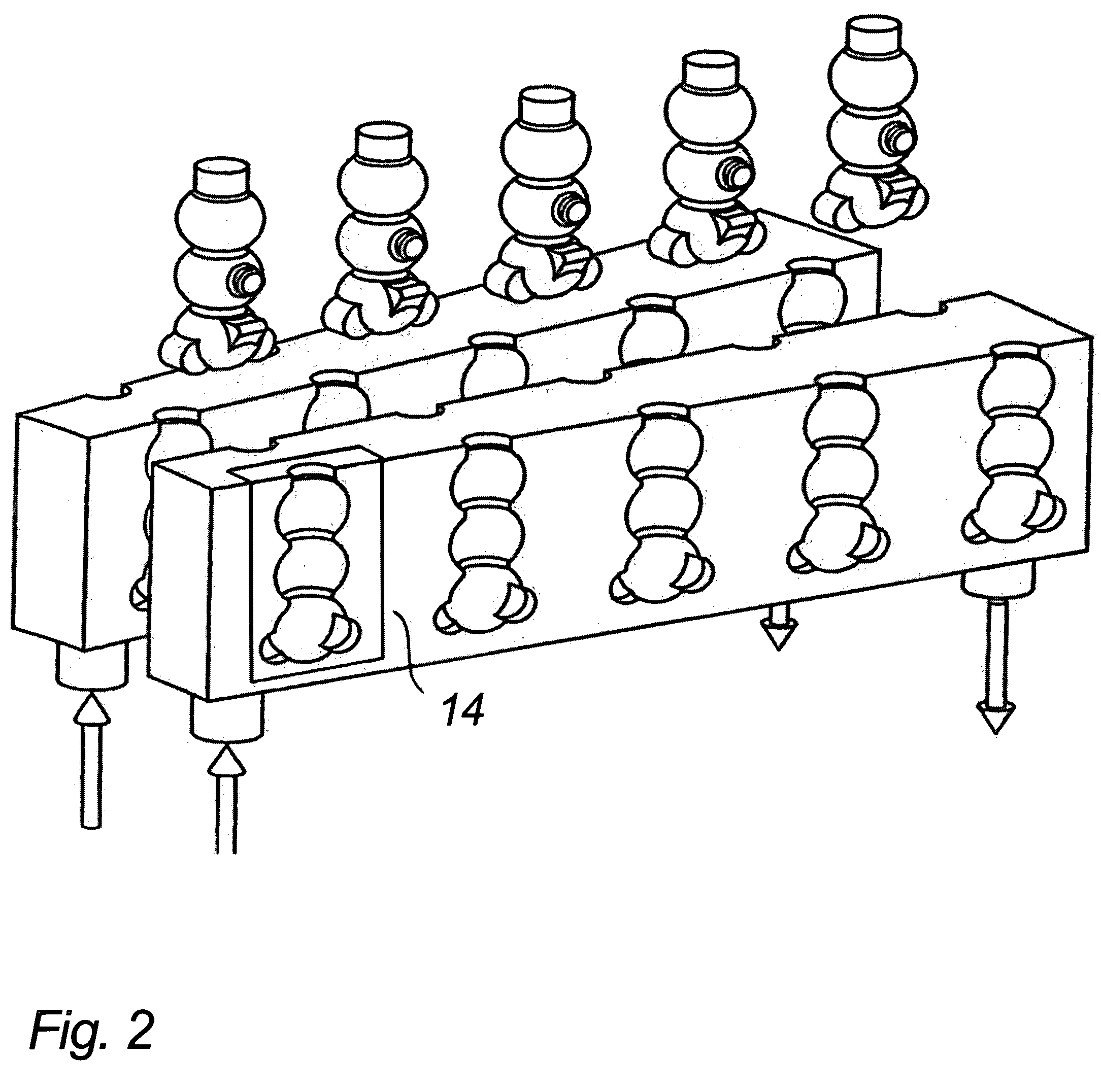
[0010] By controlling flow of the cooling or heating medium, it is possible to achieve an effective utilisation of the medium, primarily for the reason that it can be led along the surfaces which contain the forming areas at the same time that pressure loss can be reduced since the number / amount of eddy currents are limited. The flow can also be controlled so that it hits surfaces at a more expedient angle, and the eddy currents are hereby limited further.
[0014] An aspect of the invention is that use is made of cooled brine as cooling medium. The cooled brine preferably has a temperature of around minus 40 degrees centigrade. Experiments have shown that at such low temperatures, a “tunnel effect” appears which, in brief, means that the cooling medium, to a high degree, maintains that structure it has when it leaves the control unit, instead of spreading out to assume fan formations in front of an opening / nozzle, for example. Providing that there are no objects with which the flow can collide, it is herewith possible to achieve a controlled flow along a surface without any great changes occurring in the flow. At the same time, the flow will be in a more controlled manner following the surface of an object if this is hit at an expedient angle, instead of forming eddies which stop, or slow down, the flow.
[0016] The invention also relates to a system where the mould boxes contain one or more control units for controlling flow of the cooling or heating medium. It is hereby possible to create a system where pressure loss for the cooling or heating medium in the system is reduced through the expedient controlling of the flow. Among other things, this makes it easier to control the flow, and herewith achieve a uniform temperature over the whole mould surface of the mould box. Also, the amount of cooling or heating medium can be limited for the reason that better utilisation is made of the cooling / heating effect of these media.
[0025] Another aspect of the invention is that the least one opening is circular or oval in shape. It is hereby possible to ensure the greatest possible continuous “tunnel effect”, in that corners / angles which naturally cause turbulence are avoided.
[0027] Yet another aspect of the invention is that the least one opening for the control unit has a shape and positioning which controls the flow of the cooling or heating medium in a direction mainly at right-angles to the direction of the flow of the cooling or heating medium at the inlet stubs. It is hereby possible to control flow down along a mould surface in a preferably elongated mould box, which ensures an even flow along the surface of the mould.

Problems solved by technology

In connection with openable moulds that typically have mutually bottom-hinged mould half parts, it is a problem to use brine as a surrounding freezing medium because small leaks can not be completely excluded.
In connection with ice freezing, it is also known to use diverse cryogene techniques, which are edible-item friendly, are also relatively complicated or expensive.
The removal of the ice-lollies from the mould half-parts requires considerable force, which among other things can be detrimental to the surface quality of the lollies.

Method used


Image

  • Method, system and mould-box for creating form-moulded items of edible ice
  • Method, system and mould-box for creating form-moulded items of edible ice
  • Method, system and mould-box for creating form-moulded items of edible ice

Examples


first embodiment

[0047]FIGS. 6a and 6b show schematic illustrations of the flow conditions in a mould box, seen from the side and from above, respectively. In FIG. 6a, it is shown how the mould box 2 is provided with a first example of a control unit 17 for controlling the flow of the cooling or heating medium 24 inside the box. The control unit 17 is placed inside the box, immediately above the inlet stub 8 where the “fresh” cooling or heating medium 19 enters the box. In order to control or lead the cooling or heating medium, the unit is provided with a number of openings 18 in that side of the unit which faces down towards the outlet stub 10. In a preferred embodiment, five openings are disposed uniformly up along the side of the unit. However, a greater or smaller number of openings can also be provided. With the openings 18, an even and uniform flow of cooling or heating medium 24 is created down along the inner sides of the box 2 until the outlet stub 10 is reached, where the “used” cooling or...

third embodiment

[0050] In FIG. 7b shows a third embodiment where the control unit 22 and the discharge unit are each provided with an elongated opening 23 and 26, respectively.

fourth embodiment

[0051]FIGS. 8a and 8b show schematic illustrations of the flow conditions in a mould box, seen from the side and from above, respectively. In the mould box 2, the control unit 27 is built as an integral part of the surfaces in the box, where the two side surfaces in the box are connected with a further surface which is provided with an opening or openings 28 as most clearly shown in FIG. 8b. The surfaces surround the inlet stub 8 and ensure that the cooling or heating medium 24 is controlled through the box 2 as shown in the figures.

[0052]FIGS. 9a to 9c show different embodiments of a control unit 29, 32, 34, respectively, according to the invention. Each control unit is provided with a different type of openings. The control units are shown placed above the inlet stub 8, but separated by the bottom surface 31 of the mould box. In FIGS. 9a and 9b, it is shown that the control unit 29, 32 have openings which are placed over one another and at equal intervals from one another. In the ...


PUM

PropertyMeasurementUnit
Flow rateaaaaaaaaaa
Massaaaaaaaaaa
Flexibilityaaaaaaaaaa

Abstract

A method, a system, and a mould box for creating form-moulded items of edible ice from an ice mass. The method includes filling at least one mould created between a number of mould boxes with ice mass, and the introduction of cooling or heating medium into the mould boxes, where the flow of the cooling or heating medium is controlled by one or more control units in the mould boxes.

Description

BACKGROUND OF THE INVENTION [0001] 1. Field of the Invention [0002] The present invention relates to a method, a system and a mould-box for creating form-moulded items of edible ice from an ice mass. [0003] 2. Description of Related Art [0004] The traditional manner in which items of edible ice are produced is for a series of moulds to be conveyed extending downwards in a freezing bath, typically salt-brine, past a filling station and thereafter, a section for an adequate period of time in order that the ice items can at least be shell-frozen, after which the moulds are lifted over and conveyed further along a shorter section in a heating bath to achieve the thawing for freeing the ice item for subsequent detachment from the mould. This technique requires that the ice items are freely extractable, i.e. that the moulds are configured internally with mould slip. [0005] There is a considerable market for “3D-products”, i.e., edible ice items which do not appear with precisely this slip...

Claims


Application Information

Patent Timeline
IPC IPC(8): A23G3/02A23G9/08A23G9/22
CPCA23G9/083A23G9/228A23G9/221
Inventor HERMANSEN, CARSTEN
Owner TETRA LAVAL HLDG & FINANCE SA
Learn More