
Total reflection prism for projector

a technology of projectors and prisms, applied in projectors, mountings, instruments, etc., can solve the problems of deteriorating increasing fabrication costs, and achieve the effects of maintaining compactness of optical systems, improving image contrast, and increasing the size of prisms

Inactive Publication Date: 2005-12-15
FUJI PHOTO OPTICAL CO LTD
View PDF9 Cites 12 Cited by
  • Summary
  • Abstract
  • Description
  • Claims
  • Application Information

AI Technical Summary

Benefits of technology

[0009] It is an object thereof to provide a total reflection prism for restraining stray light from being generated by reflecting OFF light by an edge line portion without accompanied by large-sized formation of the prism.
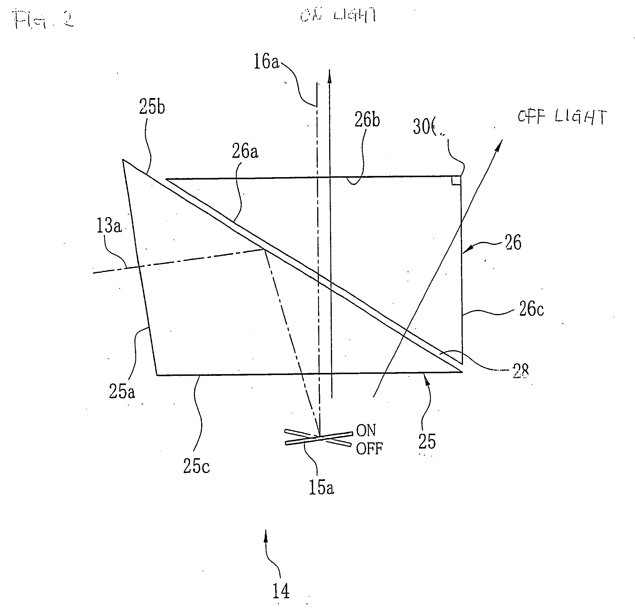
[0012] According to the invention, the edge line portion present in the region for passing OFF light is constituted by the sharp edge and therefore, OFF light constituting stray light by being reflected by the edge line portion is not generated, an influence of ghost projected to the projected image is eliminated, and contrast of the image can be improved. Further, it is not necessary to increase a size of the prism and therefore, compactness of the optical system can be maintained and fabrication cost can be prevented from being increased.

Problems solved by technology

The total reflection prism is provided with the edge line portion in a region of passing OFF light and therefore, there poses a problem that OFF light is inwardly reflected by the edge line portion to constitute stray light and ghost is brought about in a projected image.
Further, although according to the total reflection prism described in JP-A-2002-6257, the edge line portion can be escaped from the region of passing OFF light, since the prism is large-sized, there is brought about a drawback that compactness of an optical system is deteriorated and fabrication cost is increased.

Method used


Image

  • Total reflection prism for projector
  • Total reflection prism for projector
  • Total reflection prism for projector

Examples


Embodiment Construction

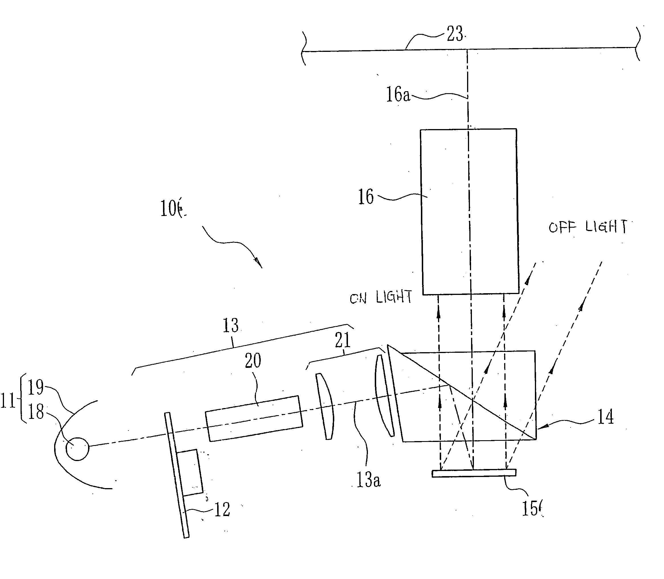
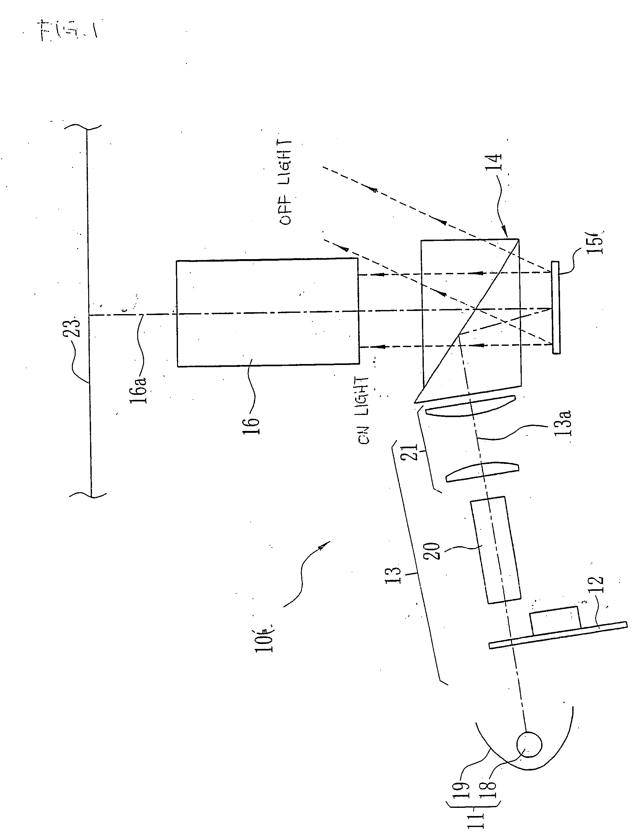
[0031] In FIG. 1, a projector 10 is provided with a light source apparatus 11, a color wheel 12, an illuminating optical system 13, a total reflection prism 14, DMD 15, and a projecting optical system 16. The color wheel 12 is arranged with respective color filters for transmitting only red color light, green color light, blue color light on a circular disk constituting a base plate at predetermined intervals in a circumferential direction. By rotating the color wheel 12, white color from the light source 18 is separated into colors by a unit of predetermined time period and is incident on the illuminating optical system 13.

[0032] The illuminating optical system 13 comprises a rod integrator 20 and a relay lens 21. The rod integrator 20 comprises, for example, glass formed in a shape of a quadrangular prism and light transmitted through the color wheel 12 is incident thereon. Light incident on the rod integrator 20 is totally reflected by a plurality of times at inside thereof to c...


PUM


Abstract

A total reflection prism includes two prisms having a shape of a triangular prism of a first prism and a second prism. The first prism includes an illuminating light incident face, a total reflection face and a panel reference face. The second prism includes an image light incident face on which image light is incident from the first prism, an image light emitting face from which image light is emitted, and a side end face. An edge line portion of a sharp edge is formed between the image light emitting face and the side end face and therefore, a light amount of OFF light reflected by the edge line portion and projected to a screen becomes extremely smaller than a light amount of ON light and does not effect an influence on quality of a projected image.

Description

[0001] This application is based on Japanese Patent application JP 2004-171633, filed Jun. 9, 2004, the entire content of which is hereby incorporated by reference. This claim for priority benefit is being filed concurrently with the filing of this application. BACKGROUND OF THE INVENTION [0002] 1. Technical Field of the Invention [0003] The present invention relates to a total reflection prism preferable for a projector for projecting an image to a screen by using a digital micromiror device as an image display panel. [0004] 2. Description of the Related Art [0005] Attention is attracted to a reflection type projector having a digital micromirror device (DMD) as an image display panel. DMD is provided with a number of micromirrors aligned in a matrix shape and an inclination of each micromirror is switched to ON position and OFF position based on a control signal. Light (ON light) incident on a micromirror at the ON position is reflected to a projecting optical system and light (OF...

Claims


Application Information

Patent Timeline
Patent Type & Authority Applications(United States)
IPC IPC(8): G02B5/04G03B21/00
CPCG02B5/04
Inventor KAWAAI, SATORUSHIMIZU, HITOSHI
Owner FUJI PHOTO OPTICAL CO LTD
Learn More