Common plenum and air intake airflow management for telecom equipment

a technology of air intake and air flow management, which is applied in the direction of electrical equipment, cooling/ventilation/heating modification, electrical apparatus, etc., can solve the problems of ineffective heat removal system, insufficient high-speed air, and insignificant improvement of air flow

Inactive Publication Date: 2005-12-15
NORTEL NETWORKS LTD
View PDF7 Cites 74 Cited by
  • Summary
  • Abstract
  • Description
  • Claims
  • Application Information

AI Technical Summary

Benefits of technology

[0014] According to another aspect of the invention, a telecommunications equipment assembly comprises an external housing having a front end, a back end, a vertical first side panel, a vertical second side panel opposite the first side panel, a bottom end section and a top end section. At least one output port is formed in the top end section and two inlet ports are formed in the bottom section and located on opposite sides of the bottom section. A fan holding device is mounted in the top end section and two or more fans are mounted on this fan holding device. An interior vertical wall is mounted in the external housing so as to extend substantially perpendicular to the first and second side panels. This vertical wall is positioned between and is spaced from the front and the back of the housing and has a upward edge spaced below the fa

Problems solved by technology

High velocity air is not enough though.
A heat removal system will be ineffective if cooling air does not reach a substantial portion of heated components in the chassis.
If, as in many electronics systems, the fan is not centrally located, air flow will not be significantly improved, if at all, in portions of

Method used


Image

  • Common plenum and air intake airflow management for telecom equipment
  • Common plenum and air intake airflow management for telecom equipment
  • Common plenum and air intake airflow management for telecom equipment

Examples


Embodiment Construction

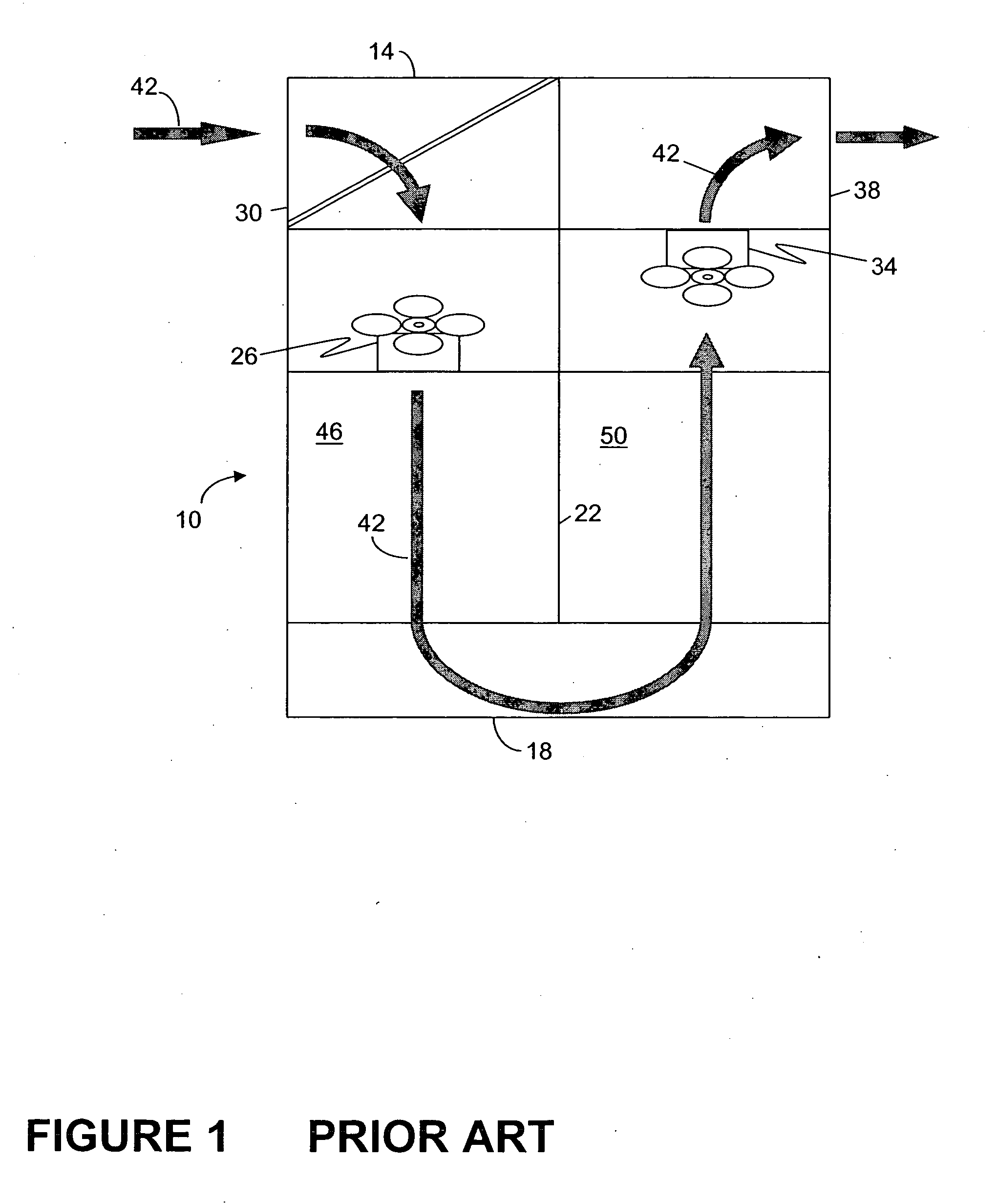
[0027] An example of a prior art fan cooling system is illustrated in FIG. 1. Housing or chassis 10 has a top wall 14 and a bottom wall 18. A divider mechanism 22 for the chassis 10 extends downwardly from the wall 14. In this prior art system, intake fan 26 draws in air from input port 30. On the opposite side of the divider mechanism 22 there is an exhaust fan 34 which exhausts air through output port 38. This configuration allows the fans 26 and 34 to move air through the chassis 10 in the direction indicated by arrows 42. As air flows through the chassis 10, electronic apparatuses located in regions of the chassis (e.g. regions 46 and 50) are cooled by the passing air.

[0028] While the above described fan cooling system may be satisfactory in uniformly cooling electronic apparatuses in the chassis 10 when the fans 26 and 34 are working properly, cooling will be non-uniform in the event of fan failure. For example, if the fan 26 fails, only the fan 34 will remain in operation. Th...


PUM


Abstract

An air flow distribution system for a telecommunication equipment assembly is disclosed. The telecommunications equipment assembly includes a chassis. The chassis is formed by wall panels and includes a first side, a second side, a bottom end section, a top end section, electronic apparatuses regions and a plenum region having plenum region boundaries. The telecommunication equipment assembly also includes a first side air input port and a second side air input port in the bottom end section of the chassis. The input ports permit cooling air to be drawn into the chassis. An output port is provided in the top end section of the chassis. A fan holder is located along one of the plenum region boundaries. The fan holder receives a fan to facilitate air movement in conjunction with the plenum region. The air movement includes movement along air flow paths through the electronic apparatuses regions. The electronic apparatuses and plenum regions are located above the input ports and below the output port. The electronic apparatuses regions border another of the plenum region boundaries.

Description

FIELD OF THE INVENTION [0001] This invention relates to housings and air flow distribution systems for telecommunication equipment assemblies and, in particular, a housing and method in which a plenum region within the housing or chassis of a telecommunications equipment assembly is employed in an air flow distribution system. BACKGROUND OF THE INVENTION [0002] Most modern telecommunications equipment contain electronic components, devices or equipment mounted in a housing or chassis. The chassis is generally enclosed, with an access door, side walls, and a backplane. The chassis is enclosed to prevent stray material from entering the casing and damaging the electronic apparatus, and to prevent stray emission of electromagnetic energy. There can also be a midplane in the chassis. Although the term midplane suggests a location halfway between the backplane and the front of the chassis, this is not necessarily so. [0003] In recent years, there has been a dramatic increase in functiona...

Claims


Application Information

Patent Timeline
IPC IPC(8): H04Q1/02H05K7/20
CPCH04Q2201/06H04Q2201/10H04Q1/023H05K7/20572H04Q1/035H04Q2201/12
Inventor AZIZ, FARIDCURRIE, THOMASNICOLICI, MARKO
Owner NORTEL NETWORKS LTD
Why Eureka
Try Eureka