Ethernet-powered particle counting system

a particle counting and ethernet technology, applied in the direction of electrical appliances, instruments, material analysis, etc., can solve the problems of reliability or safety concerns, ac power is subject to outages, and the cleaning solution cannot reliably penetrate the gap between the cord and the sock

Inactive Publication Date: 2006-11-23
VENTUREDYNE LTD
View PDF24 Cites 43 Cited by
  • Summary
  • Abstract
  • Description
  • Claims
  • Application Information

AI Technical Summary

Benefits of technology

[0012] Still another object of the invention is to provide a particle counting system adapted for an installation that eliminates an AC power source conventionally used for powering the system.
[0013] Yet another object of the invention is to provide a particle counting system that communicates in a network without being limited by wiring or cabling constraints.

Problems solved by technology

A disadvantage of some conventional particle counters concerns their use of an AC line voltage through what is typically a standard AC outlet, although some conventional particle counters have also considered a use of battery power.
Such a battery system also has the disadvantage that it must eventually be connected to an external power supply for recharging the batteries.
Providing external power, such as an AC line voltage, to a particle counter causes particular problems in a sterile cleanroom, where all surfaces in the cleanroom, including those of the particle counter, must be disinfected by a process of cleaning that uses a disinfectant.
Such a cleaning solution will not reliably penetrate into the gaps between the cord and the socket.
Some disinfectant solutions are corrosive to electrical contacts, which may cause reliability or safety concerns.
AC power is subject to outages.
One solution to the power outage situation, an AC Uninterruptible Power Supply (UPS), is expensive to install and maintain for a separate instrumentation system.

Method used


Image

  • Ethernet-powered particle counting system
  • Ethernet-powered particle counting system
  • Ethernet-powered particle counting system

Examples


Embodiment Construction

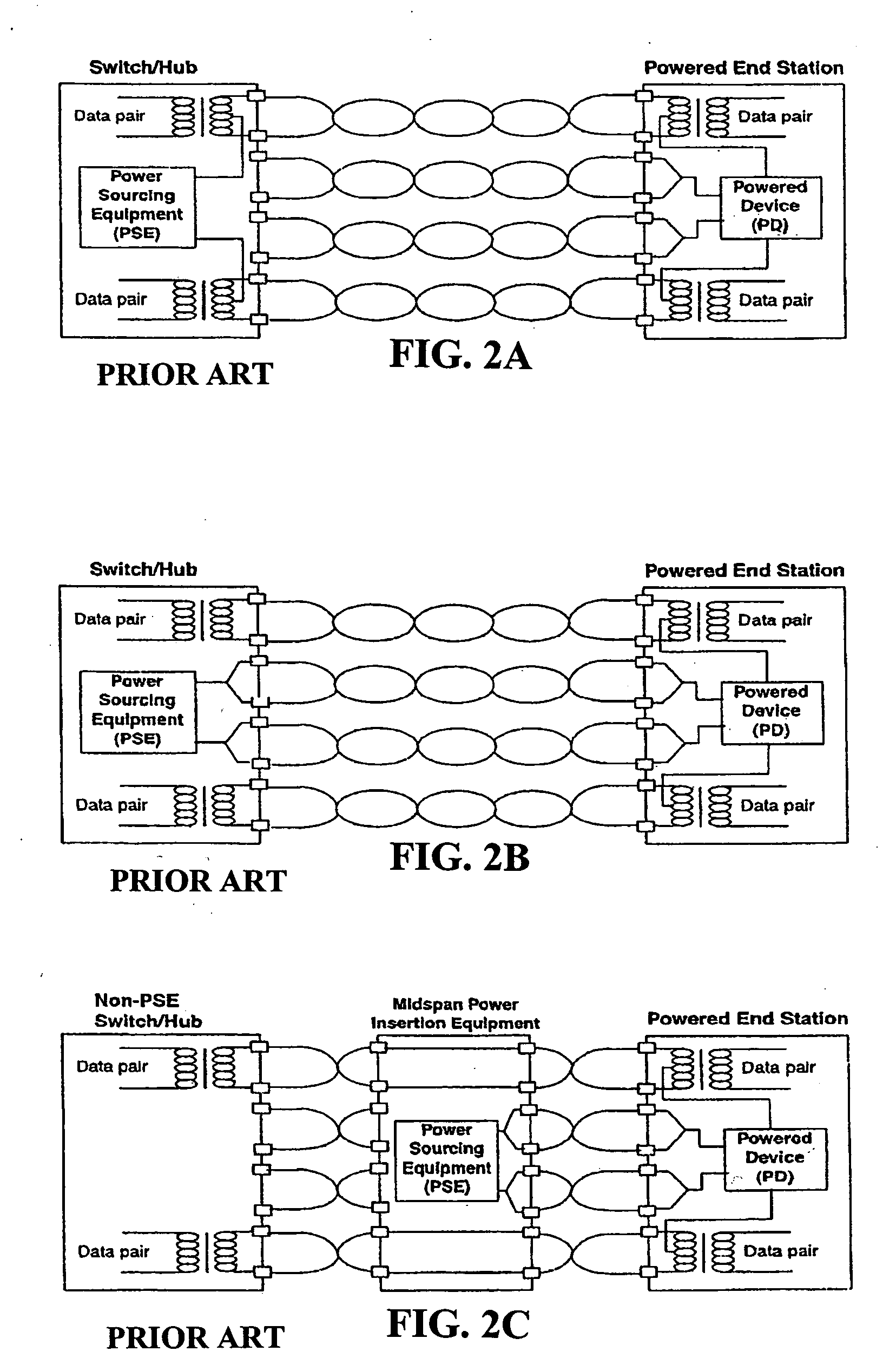
[0032] Ethernet has been developed by adoption of standards presented by the Institute of Electrical and Electronic Engineers (IEEE) and designated as IEEE 802.3. Such technology includes specifications for communications between network devices including computers and instrumentation. Transmission lines for Ethernet are also specified by IEEE, and include twisted-pair cabling that is lower in cost than coaxial cabling as a result of a use of conventional unshielded copper wires such as those used for telephones.

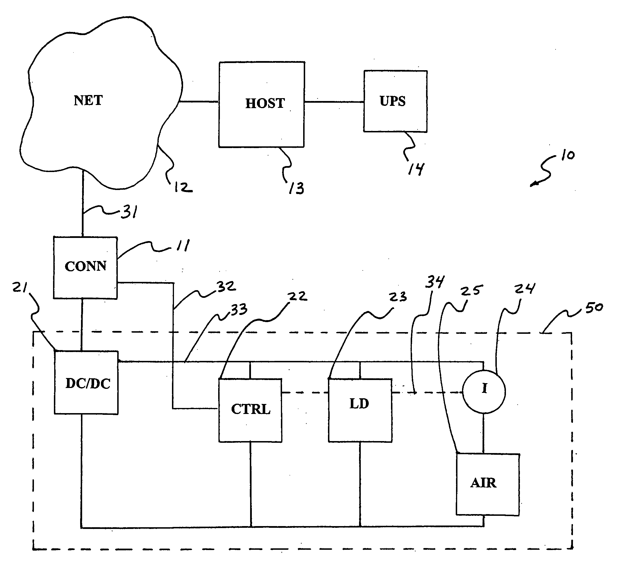
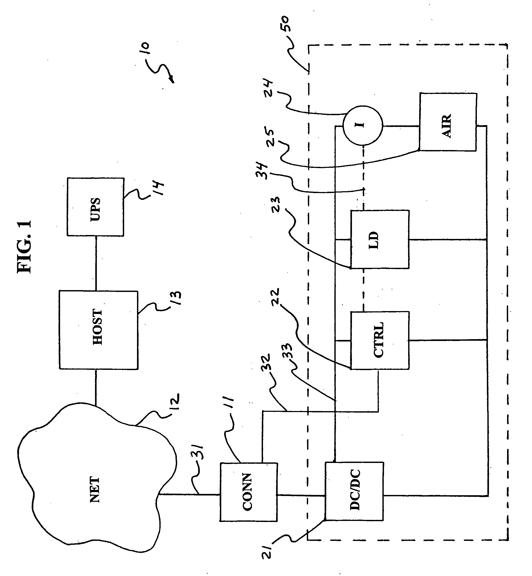
[0033]FIG. 1 schematically shows an exemplary Ethernet-powered particle counting system 10. An Ethernet subsystem 11 connects a particle counter 50 to an Ethernet type network 12 that may include a host computer 13. Host computer 13 may alternatively be located in a network that is connected indirectly to Ethernet network 12. Computer 13 preferably is connected to an uninterruptible power supply (UPS) 14 for maintaining uninterrupted electrical power to computer 13. Etherne...


PUM


Abstract

A system includes a particle counter having a data output, an Ethernet cable adapted for connecting the data output of the particle counter to a monitoring station, and a power over Ethernet (POE) type power supply structured for providing power to the particle counter via the Ethernet cable. Apparatus includes a particle counter having an air movement device powered solely by a POE supply. Apparatus may include a particle counter having an air mover, power management subsystem, and Ethernet data output, the power management subsystem for monitoring power consumption of the air mover and maintaining the power consumption below a predetermined amount, and an electrical supply for powering the particle counter via an Ethernet medium. A method includes powering a particle counter over Ethernet medium via a POE power supply, detecting microscopic particles, and producing digital data based on the detecting, and transmitting the data over the Ethernet medium.

Description

FIELD OF THE INVENTION [0001] The invention relates to particle sensing equipment and methods and, more particularly, to particle sensing systems adapted for network operation independent of wiring constraints such as those of an AC line input. BACKGROUND OF THE INVENTION [0002] Particle sensors are used in a variety of applications, including liquid and aerosol particle counting and sizing operations. Such systems typically utilize a light source such as an infrared or HeNe laser for illuminating a sample space of a liquid or aerosol flow. The laser light is scattered by the particles in the flow sample, and a photo detector type sensor is used for receiving and analyzing the scattered light, such as for determining particle counts and / or sizes. Extinction type sensors may also be used for detecting shadows rather than scattered light. Such sensors may include collection optics, a photo detector, circuitry for converting detected scattered light or shadows to electrical signals, a ...

Claims


Application Information

Patent Timeline
Patent Type & Authority Applications(United States)
IPC IPC(8): H01L21/00
CPCG01N15/1227G01N2035/00881G01N35/00871
Inventor CHANDLER, DAVID L.
Owner VENTUREDYNE LTD
Why Eureka
Try Eureka