Electric vehicle with regeneration

a technology of electric vehicles and regeneration, applied in the direction of machines/engines, propulsion by batteries/cells, transportation and packaging, etc., can solve the problems of reducing the efficiency of transportation of people and goods, and reducing the use of fossil fuel

Inactive Publication Date: 2006-12-07
DONAHUE BRAD
View PDF25 Cites 42 Cited by
  • Summary
  • Abstract
  • Description
  • Claims
  • Application Information

AI Technical Summary

Problems solved by technology

For a long while, it has been a challenge to efficiently transport people and goods.
In all, modern modes of powering a vehicle require fossil fuel that is becoming move expensive will at some date deplete.
Unfortunately, by the nature of vehicles, it is difficult to efficiently power a moving device directly with this generated electricity unless a power delivery infrastructure is in place.
In some examples such as electric trains, subways and busses, electricity has been used to power vehicles, but power must be continuously provided to these vehicles by overhead lines or a “third rail”—an infrastructure not easily duplicated on suburban streets, highways and rural roads.
Various limitations in battery technology have limited their use as a primary source of energy in many vehicles such as cars, boats and planes.
Another issue is the lack of availability of ubiquitous power sources and unfriendly recharge timing.
There are no “recharge stations” analogous to “gas stations.” Even if there were, it usually takes much longer, perhaps hours, to recharge a battery, making it impractical to stop and recharge on the way to work.

Method used


Image

  • Electric vehicle with regeneration
  • Electric vehicle with regeneration
  • Electric vehicle with regeneration

Examples


first embodiment

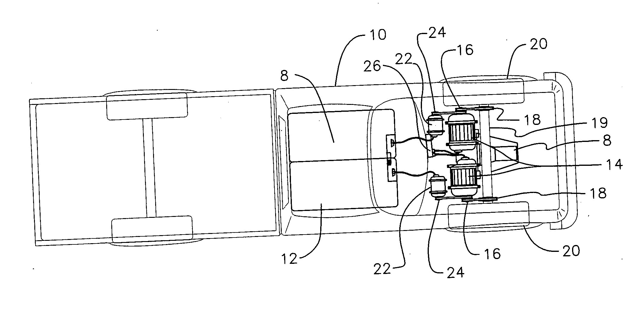
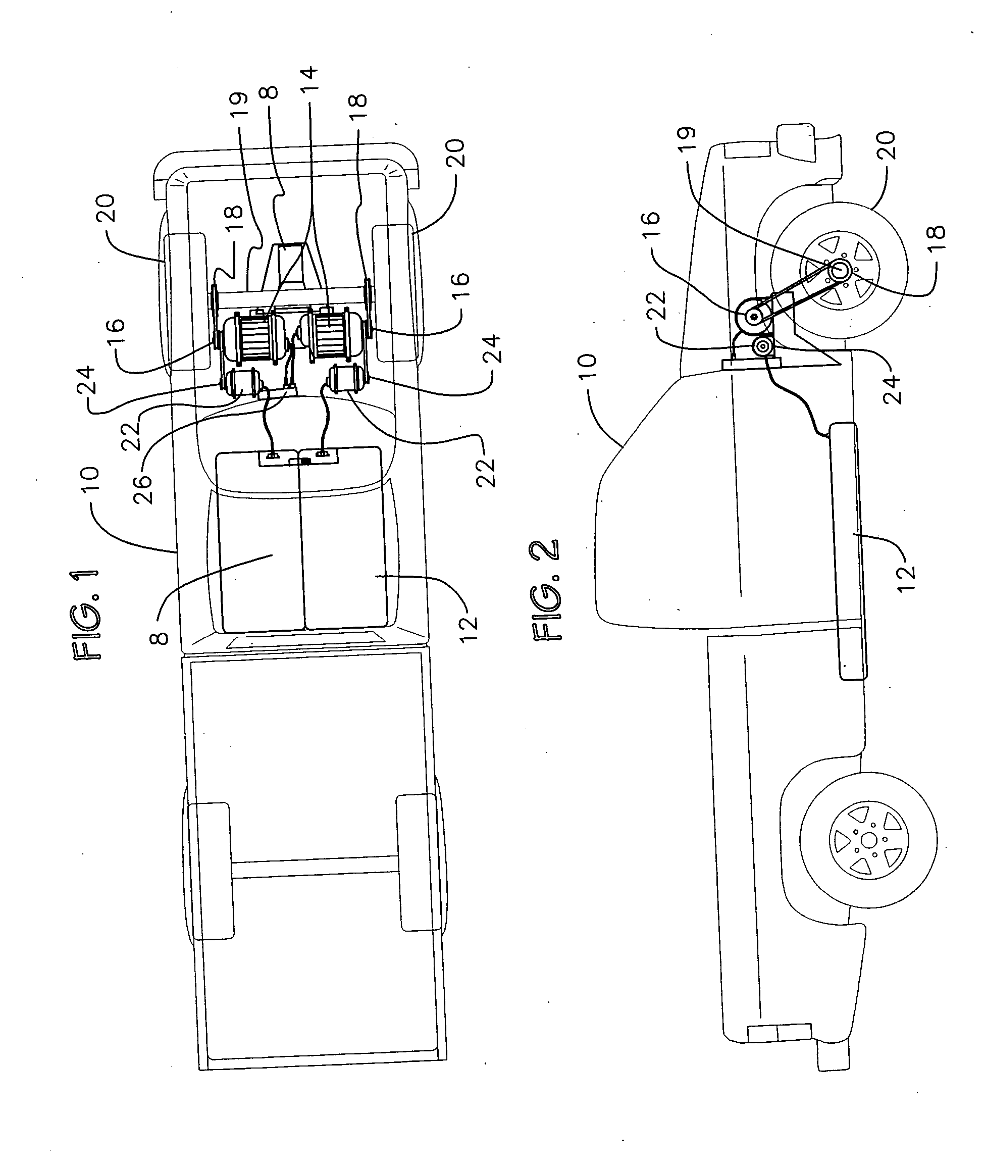
[0026] Referring to FIG. 1 and FIG. 2, a top schematic view and a side schematic view of a system of the present invention is described. A vehicle 10 has a rechargeable power source 12 that powers two motors 14 through a controller 26. The controller 26 is linked to a gas petal or other control mechanism and adjusts the speed of the vehicle 10 by controlling current flow to the motors 14. Each motor 14 has a dual pulley 16 for linking each motor 14 to both a drive pulley 18 and a generator pulley 24. In this embodiment a belt transfers rotational energy from each motor 14 to the drive pulley 18 and to the generator pulley 24, which, in turn, transfers rotational energy to the drive axle 19 and the generators 22, respectively. The axle is coupled to one or both drive wheels 20 and transfers rotational energy to the drive wheels 20 to cause the vehicle to move in a forward or backward linear direction. In some embodiments, the motors 14 are coupled to the drive train through a transmi...

second embodiment

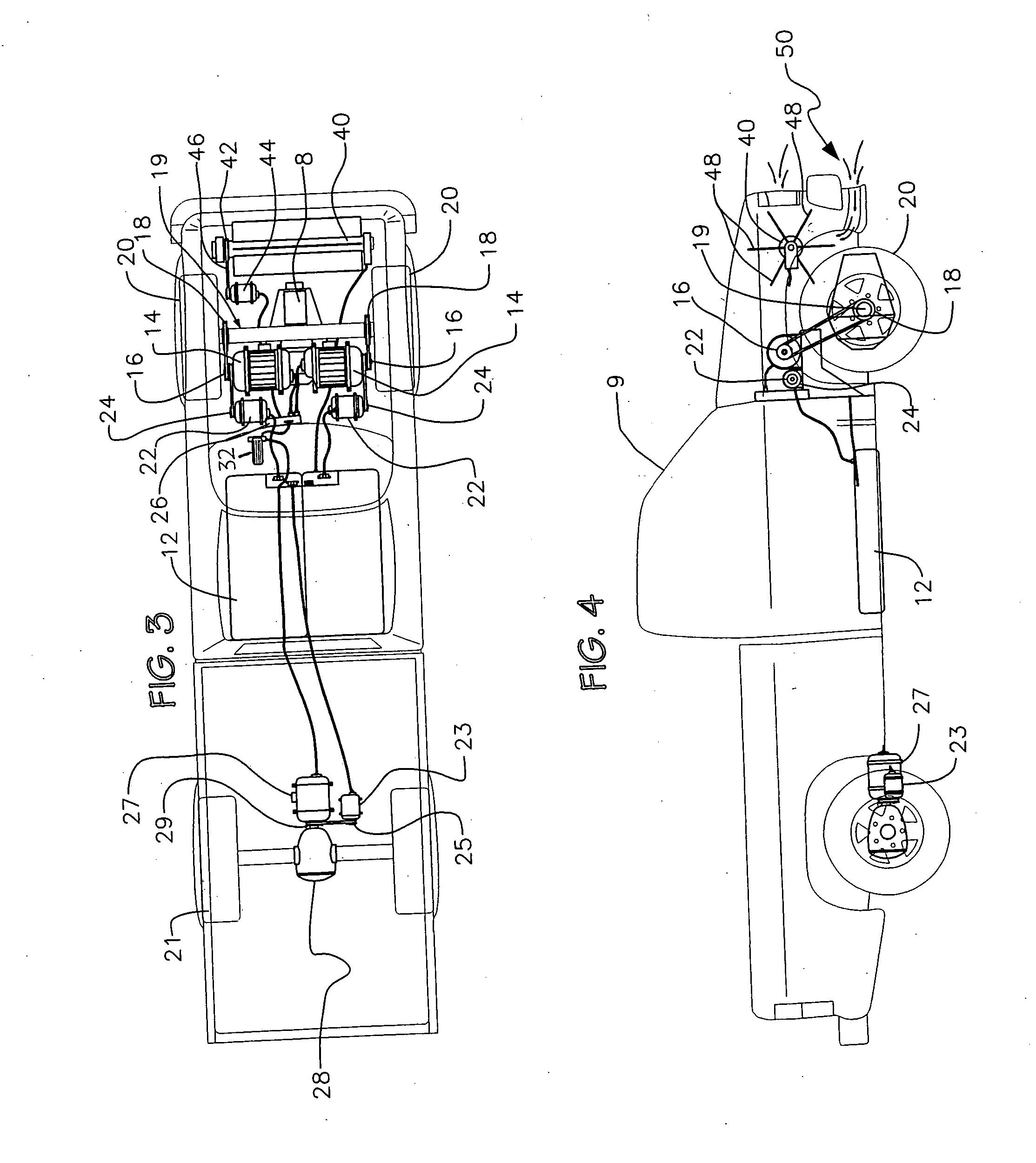
[0030] Referring to FIG. 3 and FIG. 4, a top schematic view and a side schematic view of a system of the present invention is described. A vehicle 9 has a rechargeable power source 12 that powers three motors 14 / 27 through a controller 26. The controller 26 is linked to a gas petal 32 or other control mechanism and adjusts the speed of the vehicle 9 by controlling current flow to the motors 14 / 27. Each of the first two motors 14 have a dual pulley 16 for linking each motor 14 to both a drive pulley 18 and a generator pulley 24. In this embodiment a belt transfers rotational energy from each motor 14 to the drive pulley 18 and to the generator pulley 24, which, in turn, transfers rotational energy to the drive axle 19 and the generators 22, respectively. The axle is coupled to one or both drive wheels 20 and transfers rotational energy to the drive wheels 20 to cause the vehicle to move in a forward or backward linear direction. In some embodiments, the motors are coupled to the driv...

fourth embodiment

[0037] Referring to FIG. 7 and FIG. 8, a side schematic view and an expanded view of the present invention is shown. In this embodiment a forward mounted fan 40 is connected to a fan generator 44 as shown in FIG. 3 and FIG. 4. When the vehicle is stationary, no air travels in through an air passage 50 and the blades 48 of the fan 40 do not turn. In this embodiment, each fan blade 48 has a magnet material 62 affixed on an outer edge or tip and there is a plurality of electro-magnets 60 arranged in a sequential fashion so that when the vehicle is not moving, the electro-magnets 60 can be sequentially energized, much like an electric motor, causing the fan 40 to turn. The magnetic material is steel or iron or it is a permanent magnet made from iron or powdered iron. The magnetic material may be coated to reduce or prevent rust. Since the fan 40 is linked to the fan generator 44, the fan generator 44 will turn, thereby generating electricity that is used with the electricity generated b...


PUM


Abstract

An electric powered vehicle has a rechargeable power source coupled to at least one electric motor through a controller. The motor(s) are coupled to a drive train for converting the rotational movement of the motor(s) into linear motion of the vehicle. At least one generator is coupled to the motor(s) for generating a first electric potential for recharging the power source. On the front surface of the vehicle is an air passage that channels air movement to a fan when moving in a forward motion. The fan rotates in response to the air movement and is coupled to a fan generator that turns in response, generating a second electric potential for recharging the power source. The tips of the fan blades are equipped with magnetic material and a series of electro-magnets are configured in proximity of the blades so they can be sequentially energized in absence of air movement to rotate the fan and generating the second electric potential in absence of air movement. The motor(s) and generators will function as a braking system to slow the vehicle when needed and generate electric potentials for charging the power source.

Description

BACKGROUND OF THE INVENTION [0001] 1. Field of the Invention [0002] This invention relates to the field of electric powered vehicles and more particularly to a system for powering electric vehicles with power generation for recharging a battery. [0003] 2. Description of the Prior Art [0004] For a long while, it has been a challenge to efficiently transport people and goods. Early transportation utilized animals, wind power or human energy to leverage wheels, gears, sails, pedals and the like to move a vehicle containing people and / or cargo. Later, fossil fuels or natural resources were burned to create steam which could be used to power a vehicle such as burning wood or coal in a steam driven locomotive. The combustion engine was invented, using fossil fuel to directly push a piston, creating energy of motion to move a vehicle. For some rare cases, nuclear energy has been used to power a vehicle. In all, modern modes of powering a vehicle require fossil fuel that is becoming move ex...

Claims


Application Information

Patent Timeline
Patent Type & Authority Applications(United States)
IPC IPC(8): B60K16/00
CPCB60K16/00B60L2200/26B60L7/12B60L8/006B60L11/1805B60L2200/10B60L2200/32B60L2200/36F03D9/002F03D11/04F05B2240/941Y02E10/728Y02T10/7005Y02T10/7083Y02T10/90Y02E10/725B60K2016/006F03D13/20F03D9/25B60L50/52Y02E10/72Y02T10/7072Y02T10/70F03D9/32
Inventor DONAHUE, BRAD
Owner DONAHUE BRAD
Why Eureka
Try Eureka