
Linear light source for enhancing uniformity of beaming light within the beaming light's effective focal range

a beaming light and beaming light technology, applied in the field of linear light sources, can solve the problems of inability to accurately output pictures, limited uniformity control, and inability to achieve diffusion and scattering, so as to improve the definition and accuracy of scanning

Active Publication Date: 2005-12-15
PIXON TECH CORP
View PDF15 Cites 96 Cited by
  • Summary
  • Abstract
  • Description
  • Claims
  • Application Information

AI Technical Summary

Benefits of technology

[0008] It is therefore an objective to provide a linear light source that can be applied to the target in order to improve the definition and accuracy of scanning.
[0009] It is therefore another objective to provide a linear light source for enhancing the uniformity of beaming light within the beaming light's effective focal range.
[0010] It is therefore a further objective to provide a linear light source with greater emitted or beaming light uniformity that can accurately detect the target without loss caused by uneven or non-uniform intensity.
[0011] It is therefore a further objective to provide a linear light source with high intensity that can repeatedly reflect light in order to optimally conserve the light energy and greatly enhance the intensity.
[0012] The present invention discloses a light guide assembly with improved intensity, uniformity and enhanced uniformity of beaming light within effective beaming light focal range. The light guide assembly comprises a light guide bar that connects to a light source assembly. The light source assembly comprises, for example, a single LED or plurality of LEDs in an LED package. The light source is positioned adjacent to a light-receiving end of the light guide bar. The light guide bar is encased in a reflective housing such as a reflective sleeve or reflective windowed box. One surface of the light guide bar is a light-scattering / light-emission surface where the light exits.

Problems solved by technology

If the intensity or uniformity of the light source is patchy, the output picture will not be accurate.
These designs are easier to be molded or fabricated, but the efficiency of light propagation in terms of diffusion and scattering or uniformity control is limited.

Method used


Image

  • Linear light source for enhancing uniformity of beaming light within the beaming light's effective focal range
  • Linear light source for enhancing uniformity of beaming light within the beaming light's effective focal range
  • Linear light source for enhancing uniformity of beaming light within the beaming light's effective focal range

Examples


Embodiment Construction

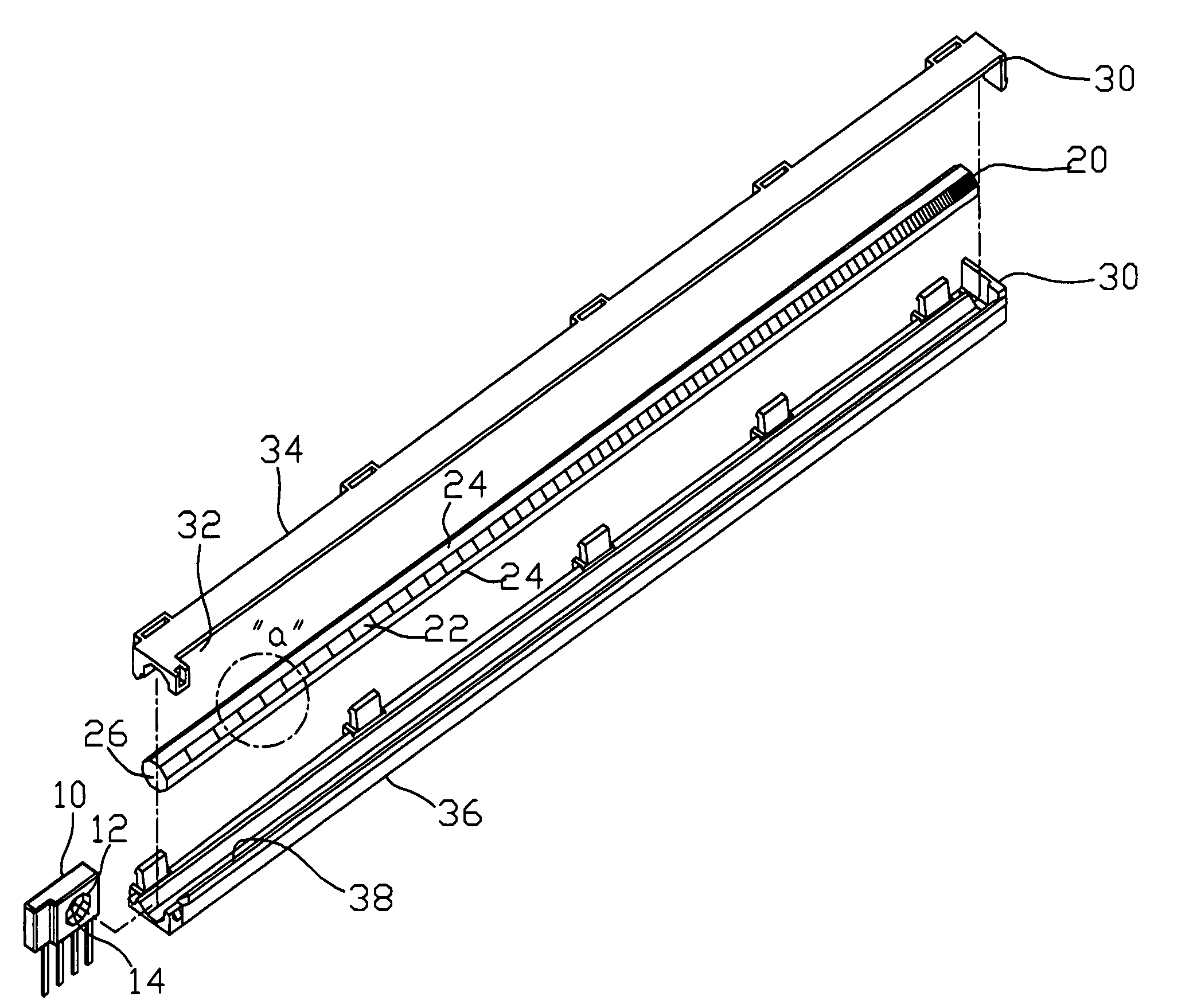
[0033] The present invention provides a light guide assembly with improved emitted light intensity and uniformity and with improved uniformity of beaming light within the beaming light's effective focal range.

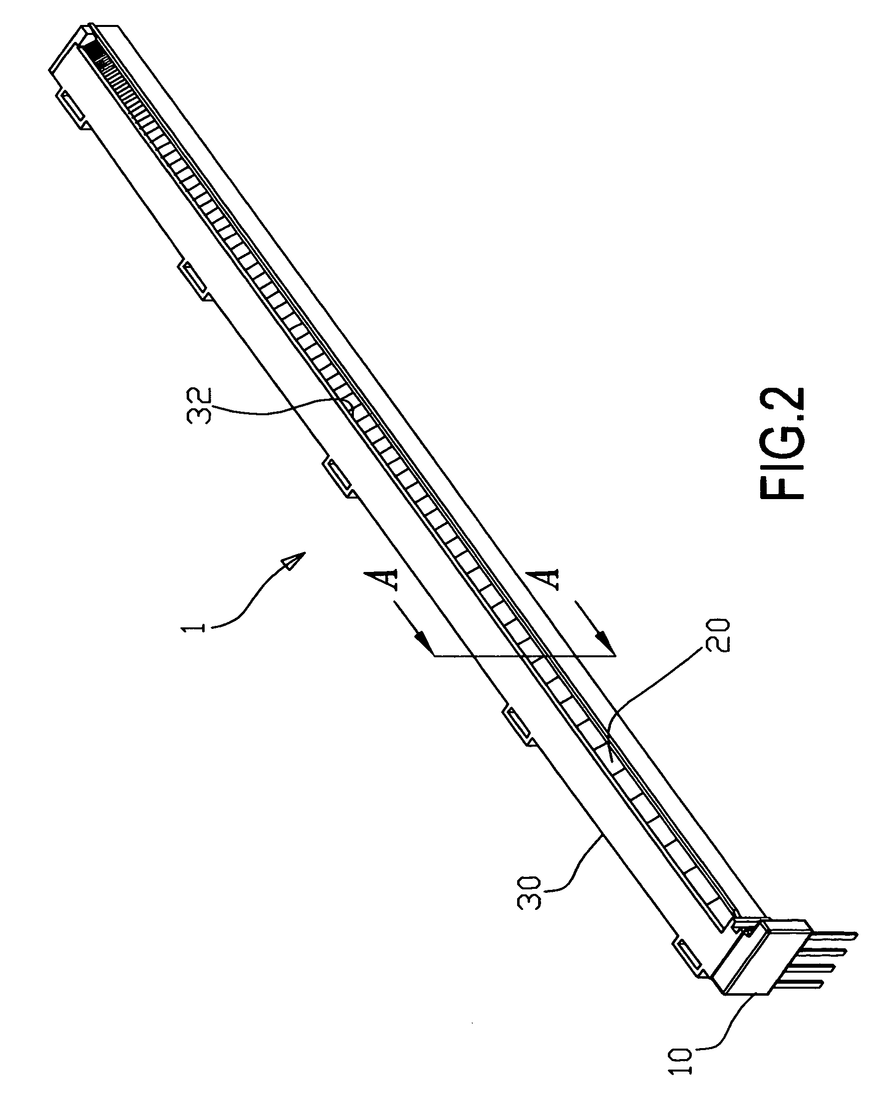
[0034] Refer to FIG. 2, which is a 3-dimentional diagram of a light guide assembly according to an embodiment of the present invention.

[0035] As shown in FIG. 2, the light guide assembly 1 comprises a light source assembly 10, a light guide bar 20 and a reflecting sleeve 30 surrounding the light guide body 20. Light from the light guide bar 20 is emitted through an emission opening 32 in the reflecting sleeve 30.

[0036] Also refer to FIG. 3, which is an exploded view of a light guide assembly according to an embodiment of the present invention.

[0037] The light source assembly 10 of the light guide assembly 1 comprises an opening 12 which corresponds in shape to the shape of the light guide bar 20. The light guide bar 20 is received in the opening 12 and allows the light guid...


PUM


Abstract

A light guide assembly, as a linear light source, includes a light guide bar connected to a light source assembly and a reflective housing encasing the light guide bar. One surface of the light guide bar is a light-scattering / light-emission surface, and other surfaces are all reflective. The emission plane has gradually changing indentations for adjusting the light refractive and reflecting indexes to ensure the light uniformity. The reflective housing covering the light guide bar is used for enhancing the light reflection and intensity. An opening is formed in the reflective housing corresponding to the emission plane of the light guide bar, and a reflecting flange is formed at one side of the opening. Combined with the sloping and notched emission plane, light with high intensity and uniformity can be obtained, and the uniformity of beaming light within the beaming light's effective focal range can also be improved.

Description

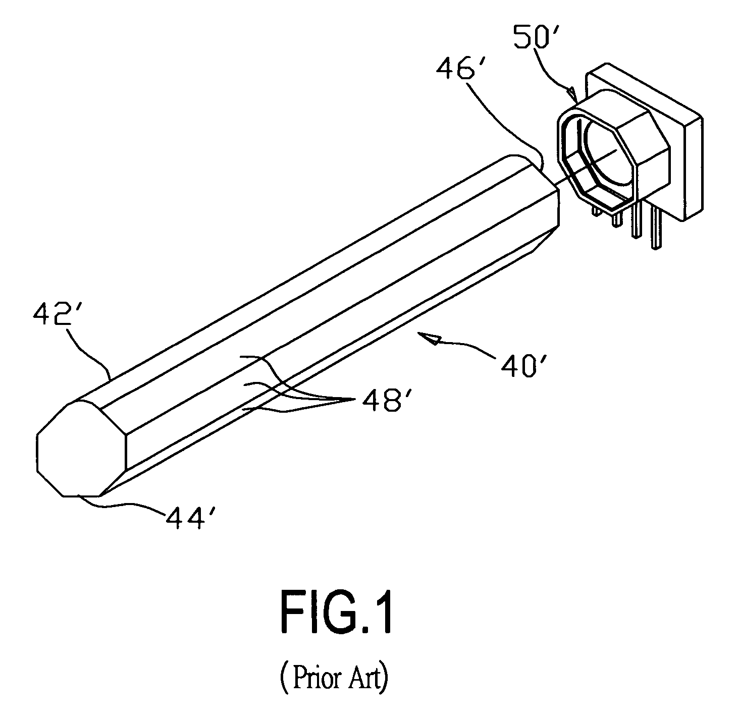
CROSS-REFERENCE TO RELATED APPLICATIONS [0001] This application is a continuation-in-part of U.S. patent application Ser. No. 10 / 857,873, filed Jun. 2, 2004 in the U.S. Patent and Trademark Office, the disclosures of which are incorporated herein by reference.BACKGROUND OF INVENTION [0002] 1. Field of the Invention [0003] The invention relates to a linear light source, and more particularly, to a linear light source having a light guide bar with a sloped and notched light emitting surface and an external reflective housing, which enhances uniformity of beaming light within the beaming light's effective focal range in addition to the overall improvements on light intensity and uniformity. [0004] 2. Description of Related Art [0005] Scanners, facsimile machines and multifunction peripherals are popularly used in daily life. This type of equipment generally utilizes a linear light source to illuminate the target. Imaging quality of the scanned target is greatly related to the performan...

Claims


Application Information

Patent Timeline
Patent Type & Authority Applications(United States)
IPC IPC(8): F21V7/04H01L33/60H04N1/028
CPCH04N1/02815H04N1/02825H04N1/0289H04N1/0284H04N1/02885H04N1/02835
Inventor WU, RONG YAWCHEN, SHIH-CHEYEN, CHIH-MING
Owner PIXON TECH CORP
Learn More