Speaker device and method of manufacturing the speaker device

a speaker device and manufacturing method technology, applied in the direction of deaf-aid sets, transducer details, electrical transducers, etc., can solve problems such as clogging through holes, and achieve the effect of improving the appearance of the speaker device and preventing the occurrence of abnormal sound

Inactive Publication Date: 2005-12-15
PIONEER CORP +1
View PDF0 Cites 14 Cited by
  • Summary
  • Abstract
  • Description
  • Claims
  • Application Information

AI Technical Summary

Benefits of technology

[0015] In the above method of manufacturing the speaker device, the resin frame is disposed on the workbench, and the magnetic circuit having the plate is mounted onto the resin frame. Subsequently, the adhesive agent is applied between the outer peripheral portion of the plate and the inner wall of the resin frame. Since the resin frame has the through hole, the recess portion and the slit, the adhesive agent is dried in the state that the inner side and the outer side of the frame communicate with each other through the recess portion and the slit. Thereby, the bubble due to the adhesive agent can be prevented. Therefore, the corrosion of the magnetic circuit system and the occurrence of the abnormal sound can be prevented, and the reinforcement of the outer peripheral edge portion of the plate can be stably performed.
[0016] In a form of the above method of manufacturing the speaker device, a name plate may be attached onto the recess portion after the adhesive agent is dried. After the adhesive agent applied between the outer peripheral edge portion of the plate and the inner peripheral wall of the frame is dried, the through hole becomes unnecessary. Therefore, the through hole is sealed with the nameplate, and it is prevented that the moisture enters from the outer side. In addition, attaching the name plate can make the speaker device look better.

Problems solved by technology

In the process of reinforcing the outer peripheral edge portion of the plate, if the adhesive agent is applied to the gap between the outer peripheral edge portion of the plate and the inner peripheral wall of the resin frame, the adhesive agent is dropped to the bottom surface of the resin frame along the inner peripheral wall of the resin frame, which may clog the through hole.

Method used


Image

  • Speaker device and method of manufacturing the speaker device
  • Speaker device and method of manufacturing the speaker device
  • Speaker device and method of manufacturing the speaker device

Examples


Embodiment Construction

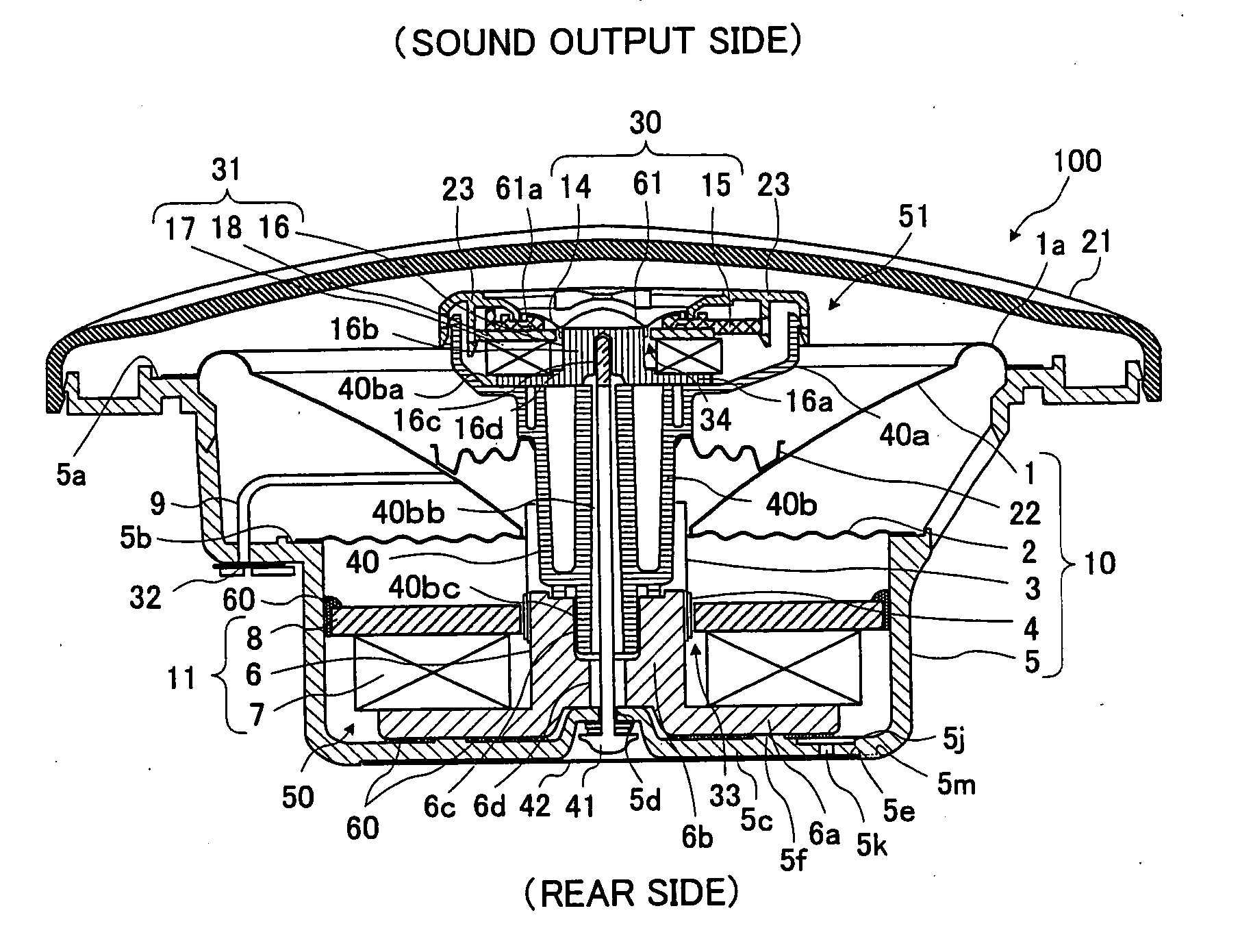
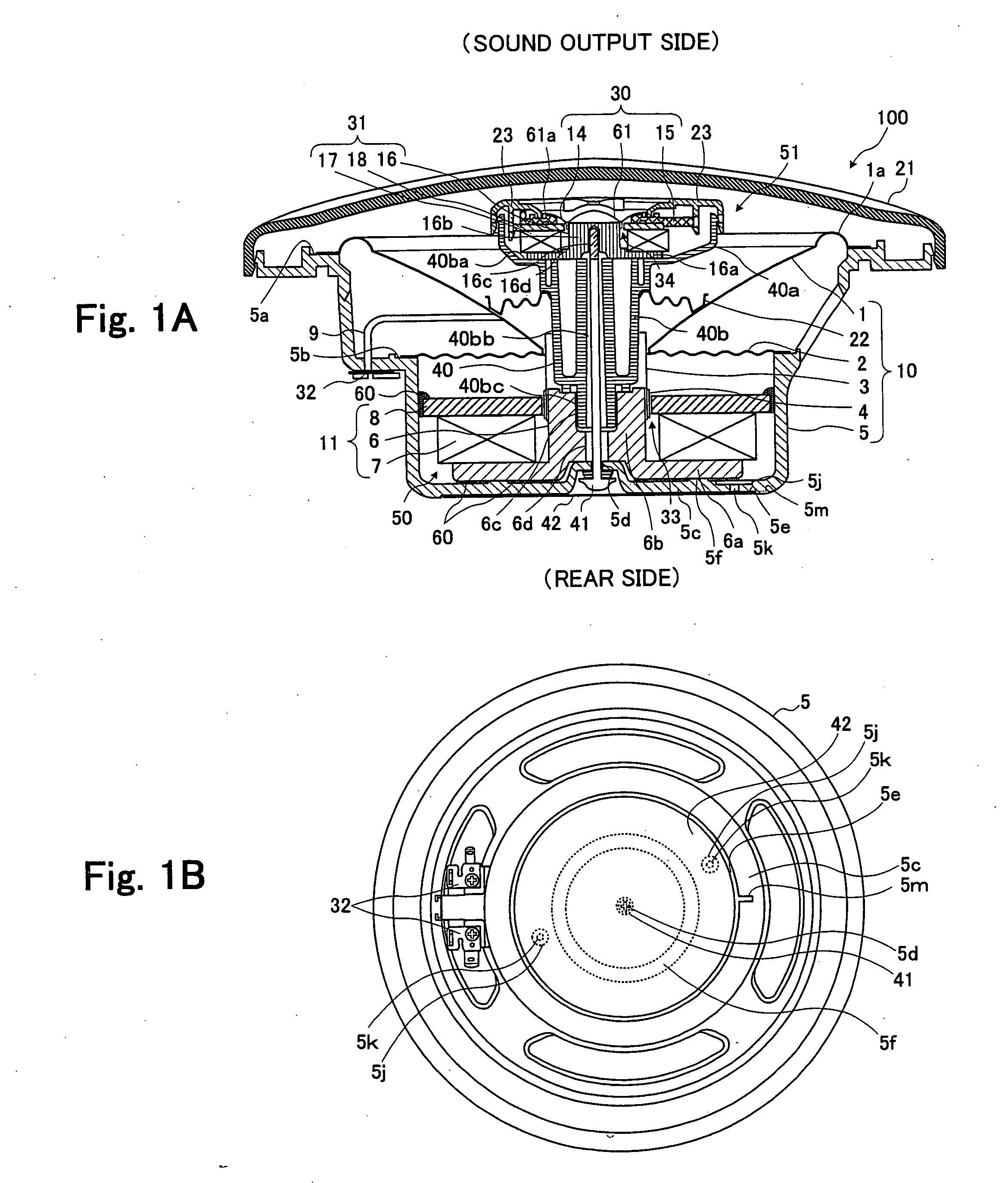
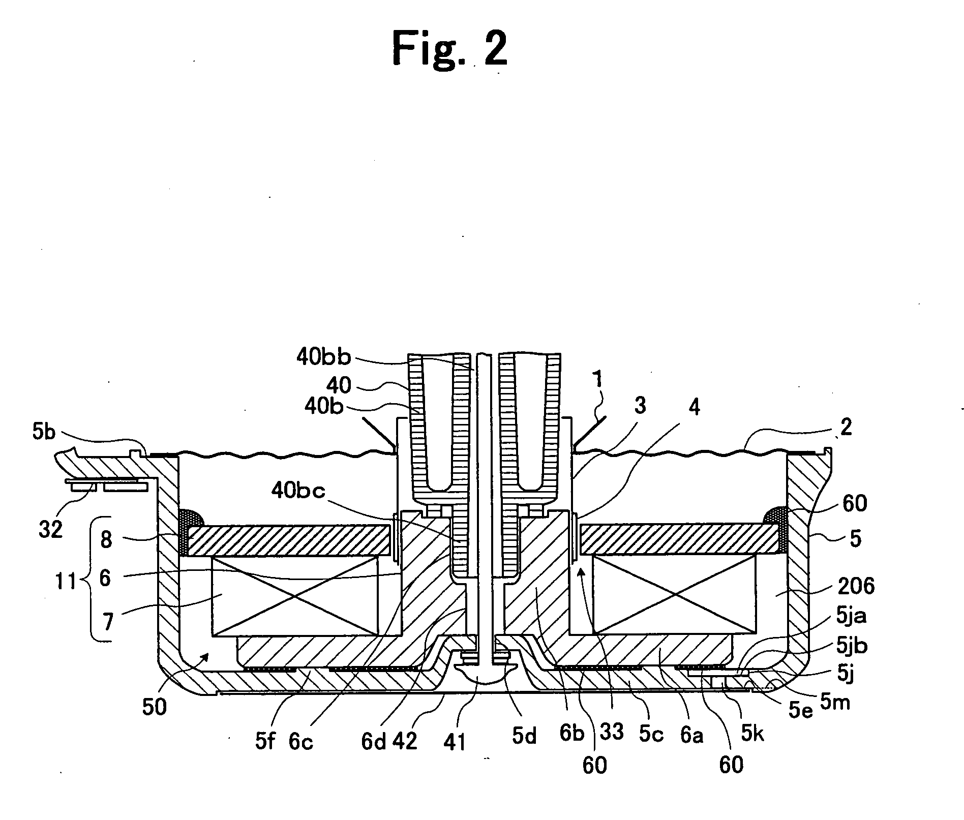
[0024] Hereinafter, preferred embodiment of the invention will be described by referring to the drawings. The speaker device of this embodiment has a configuration of the resin frame capable of preventing the bubble from occurring at the time of reinforcing the outer peripheral edge portion of the plate by the adhesive agent to form a sealed space. Thereby, the corrosion of the magnetic circuit system and the occurrence of the abnormal sound can be prevented.

[Configuration of Speaker Device]

[0025] First, in FIGS. 1A and 1B, an outline configuration of a speaker device 100 according to the embodiment of the present invention is schematically shown. FIG. 1A is a sectional view when the speaker device 100 is cut along a plane containing a central axis thereof. FIG. 1B is a rear view of the speaker device 100. The speaker device 100 in the embodiment can be used preferably as a marine speaker. As below, referring to FIGS. 1A and 1B, the configuration etc. of the speaker device 100 of ...


PUM


Abstract

A speaker device includes a magnetic circuit system having a resin frame and a plate. The frame holds the magnetic circuit system, and has a step portion, a hole portion, a recess portion and a slit. The step portion is formed on an inner surface of a peripheral edge portion of the frame, and the hole portion penetrates from a bottom surface of the step portion to the recess portion. The recess portion is formed on an outer surface of the frame. The slit is formed on the outer surface of the frame, and extends from the recess portion to the outer side. The step portion, the hole portion, the recess portion and the slit communicate with each other. Adhesive agent is applied to a gap between the outer peripheral edge portion of the plate and the inner peripheral wall of the frame.

Description

TECHNICAL FIELD [0001] The present invention relates to a configuration of a frame in a speaker device. BACKGROUND ART [0002] There is known an external magnet type speaker device in which a magnetic circuit system including a pole piece, an annular magnet disposed on a yoke of the pole piece and an annular plate disposed on the magnet is mounted onto a frame. In such the speaker device, each component of the magnetic circuit system is attached by an adhesive agent, and the magnetic circuit system is attached to an inner surface of the frame by the adhesive agent. [0003] There is known a speaker unit in which a magnet, an upper plate and a lower plate are attached to each other by a photo-curing type adhesive agent (see Japanese Patent Application Laid-Open No. 2001-231094, for example). There is also known an internal magnet type magnetic circuit for a speaker which releases the air at the time of a rust prevention treatment and removes liquid such as paint and planting liquid by p...

Claims


Application Information

Patent Timeline
Patent Type & Authority Applications(United States)
IPC IPC(8): H04R9/02H04R1/24H04R9/06H04R25/00H04R31/00
CPCH04R1/24H04R9/063
Inventor KOBAYASHI, HIROYUKIKASAHARA, KENICHIHAYASAKA, SHINICHIHIKICHI, TOSHIHIRO
Owner PIONEER CORP
Why Eureka
Try Eureka