X-ray tube and x-ray generation device

a generation device and x-ray tube technology, applied in the direction of x-ray tube gas control, x-ray tube window, x-ray tube structural circuit elements, etc., can solve the problems of abnormal discharge of x-ray inspection, and achieve accurate prevention of abnormal discharge, monitoring lifetime, and high sensitivity

Active Publication Date: 2021-03-25
ANRITSU CORP +1
View PDF0 Cites 2 Cited by
  • Summary
  • Abstract
  • Description
  • Claims
  • Application Information

AI Technical Summary

Benefits of technology

[0027]According to the present invention, it is possible to provide an X-ray tube and an X-ray generation device capable of detecting the pressure in a high vacuum region with high sensitivity and accurately preventing the occurrence of an abnormal discharge and monitoring the lifetime.

Problems solved by technology

When deterioration of the vacuum occurs, generation of an abnormal discharge due to deterioration of the vacuum causes fluctuation of X-ray intensity, thereby making it liable to cause an abnormality in the inspection using the X-ray.

Method used


Image

  • X-ray tube and x-ray generation device
  • X-ray tube and x-ray generation device
  • X-ray tube and x-ray generation device

Examples


verification example 1

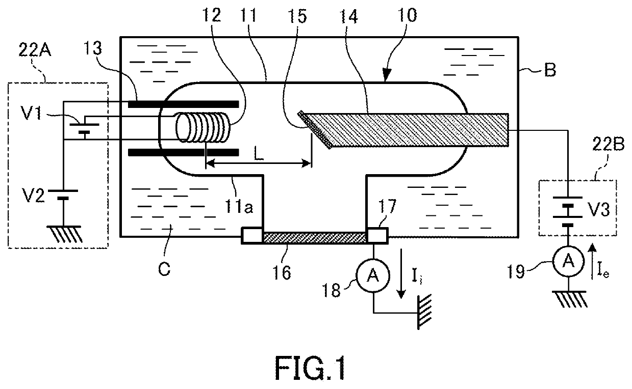
[0087]FIG. 4 shows the configuration of a system for verifying that the pressure can be measured from the ion current and the electron current detected in the X-ray tube 10 of the present embodiment.

[0088]As shown in FIG. 4, this verification system is so configured that a vacuum pump 71, a vacuum gauge 72, a gas introduction valve 73 with the divergence adjustment function, and an introduction gas tank 74 are connected to the X-ray tube 10 through a vacuum pipe 75. In this verification system, the inside of the envelope 11 of the X-ray tube 10 for test is exhausted by the vacuum pump 71 and the nitrogen gas, which is an inert gas, is intermittently introduced into the envelope 11 from the introduction gas tank 74 through the gas introduction valve 73 with the divergence adjustment function, thereby making it possible to have the inside of the envelope 11 at a predetermined vacuum state.

[0089]At the time of verification by this verification system, together with the vacuum exhaustio...

verification example 2

[0100]Therefore, as a verification example 2, an examination was conducted about the setting range of the filament side positive potential V2 and the anode side positive potential V3, in which it is possible to increase the ion current Ii at a pressure of 10−4 Pa order of magnitude, and to secure the increase of the ion current at the first power or more of the pressure that expresses in the pressure of 10−2 Pa to 1 Pa and the nonlinear increase of the electron current Ie from the certain value.

[0101]The filament side positive potential V2 may be a positive potential in order to collect ions in the ion collector. In the experiment, the positive potential V2 was set to a positive potential of 10 V to 10 V, but the change in ion current was small. Therefore, it was determined that the filament side positive potential V2 should be set to a positive potential of 100 V or less.

[0102]Next, the vacuum dependency of the ion current Ii and the electron current Ie was measured, where the fila...


PUM

PropertyMeasurementUnit
pressureaaaaaaaaaa
electric conductivityaaaaaaaaaa
electric potentialaaaaaaaaaa

Abstract

An X-ray tube, including: an envelope (11) that holds inside thereof at a predetermined pressure; a filament (12) for emitting electrons and a focus electrode (13) provided in the envelope: and a target (15) for generating X-ray provided in the envelope facing to the filament (12) and the focus electrode (13), wherein the envelope (11) has an envelope body (11a) and an X-ray window portion (16) having a higher X-rays transmissivity and a higher electric conductivity than the envelope body (11a), when the X-ray window portion (16) or the anode (14) is set to a lower electric potential than both of an electric potential of the anode (14) or the X-ray window portion (16) and an electric potential of the filament (12) and the focus electrode (13), detection of at least one of an ion current (Ii) or an electron current (Ie) through the X-ray window portion (16) or the anode (14) is possible.

Description

FIELD OF THE INVENTION[0001]The present invention relates to an X-ray tube and an X-ray generation device, and more particularly to an X-ray tube and an X-ray generation device capable of measuring the pressure in an envelope.BACKGROUND ART[0002]In an article inspection or the like for irradiating an inspection article with X-rays, generally, an X-ray tube as an X-ray generation source and an X-ray generation device provided with the X-ray tube are used.[0003]The X-ray tube is usually a high-vacuum vacuum ceiling device of, for example, about 10−4 Pa. When deterioration of the vacuum occurs, generation of an abnormal discharge due to deterioration of the vacuum causes fluctuation of X-ray intensity, thereby making it liable to cause an abnormality in the inspection using the X-ray.[0004]Then, technologies for measuring the pressure in the envelope of an X-ray tube using the electrode of an X-ray tube are conventionally known (for example, refer Patent Documents 1, 2, and 3).[0005]Su...

Claims


Application Information

Patent Timeline
Patent Type & Authority Applications(United States)
IPC IPC(8): H05G1/30H01J35/18H05G1/26
CPCH05G1/30H05G1/265H01J35/18H01J35/025H01J35/16H01J2235/18H01J2235/20H05G1/54
Inventor KOBA, HIROYUKIMORIYA, JYUNICHITAKAHASHI, YOSHIFUMIKURISU, HIROKI
Owner ANRITSU CORP
Why Eureka
Try Eureka