Speaker device

a speaker device and structure technology, applied in the direction of deaf-aid sets, transducer details, electrical transducers, etc., can solve the problems of abnormal sound and loss of vibrating system balance, and achieve the effect of preventing abnormal sound

Inactive Publication Date: 2009-09-08
PIONEER CORP +1
View PDF11 Cites 2 Cited by
  • Summary
  • Abstract
  • Description
  • Claims
  • Application Information

AI Technical Summary

Benefits of technology

[0009]When the above-mentioned speaker device is driven, the voice coil bobbin vibrates in the axial direction of the speaker device. At this time, the balance of the vibrating system is sometimes lost due to various factors, and the voice coil bobbin rolls. The fulcrum of the rolling is located at the area in the vicinity of the portion supporting the connecting member by the damper. In the speaker device, since the inner peripheral edge portion of the damper is attached to the connecting member within the constant winding width of the voice coil in the non-rolling state, the fulcrum of the rolling is positioned within the constant winding width of the voice coil. Therefore, the distance from the fulcrum of the rolling to the portion around which the voice coil of the voice coil bobbin is wound becomes short, and the voice coil bobbin hardly rolls. Even when the voice coil bobbin rolls, a moving amount of the voice coil bobbin in the lateral direction becomes small. Thus, at the time of the rolling, the contact of the voice coil and the pot type yoke can be prevented, and the contact of the voice coil bobbin and the plate can be prevented, too. Thereby, the occurrence of the abnormal sound can be prevented.
[0011]In accordance with the form, since the outer peripheral edge portion of the damper is supported by the frame within the constant winding width of the voice coil, the entire portion of the damper is disposed within the constant winding width of the voice coil. At the time of the rolling, the contact of the voice coil and the pot type yoke can be prevented, and the contact of the voice coil bobbin and the plate can be prevented, too. Therefore, the occurrence of the abnormal sound can be prevented.
[0012]In a preferred example of the above-mentioned speaker device, plural dampers may be provided, and all of the plural dampers may be attached to the connecting member within the constant winding width. Even when the plural dampers are used, by attaching all the dampers to the connecting member within the winding width of the voice coil, the contact of the voice coil bobbin at the time of the rolling can be prevented.

Problems solved by technology

At this time, a balance of the vibrating system is lost due to various kinds of factors, and the voice coil bobbin sometimes rolls.
As a result, the voice coil contacts the pot type yoke, or the voice coil bobbin contacts the plate, and an abnormal sound problematically occurs.

Method used


Image

  • Speaker device
  • Speaker device
  • Speaker device

Examples


Embodiment Construction

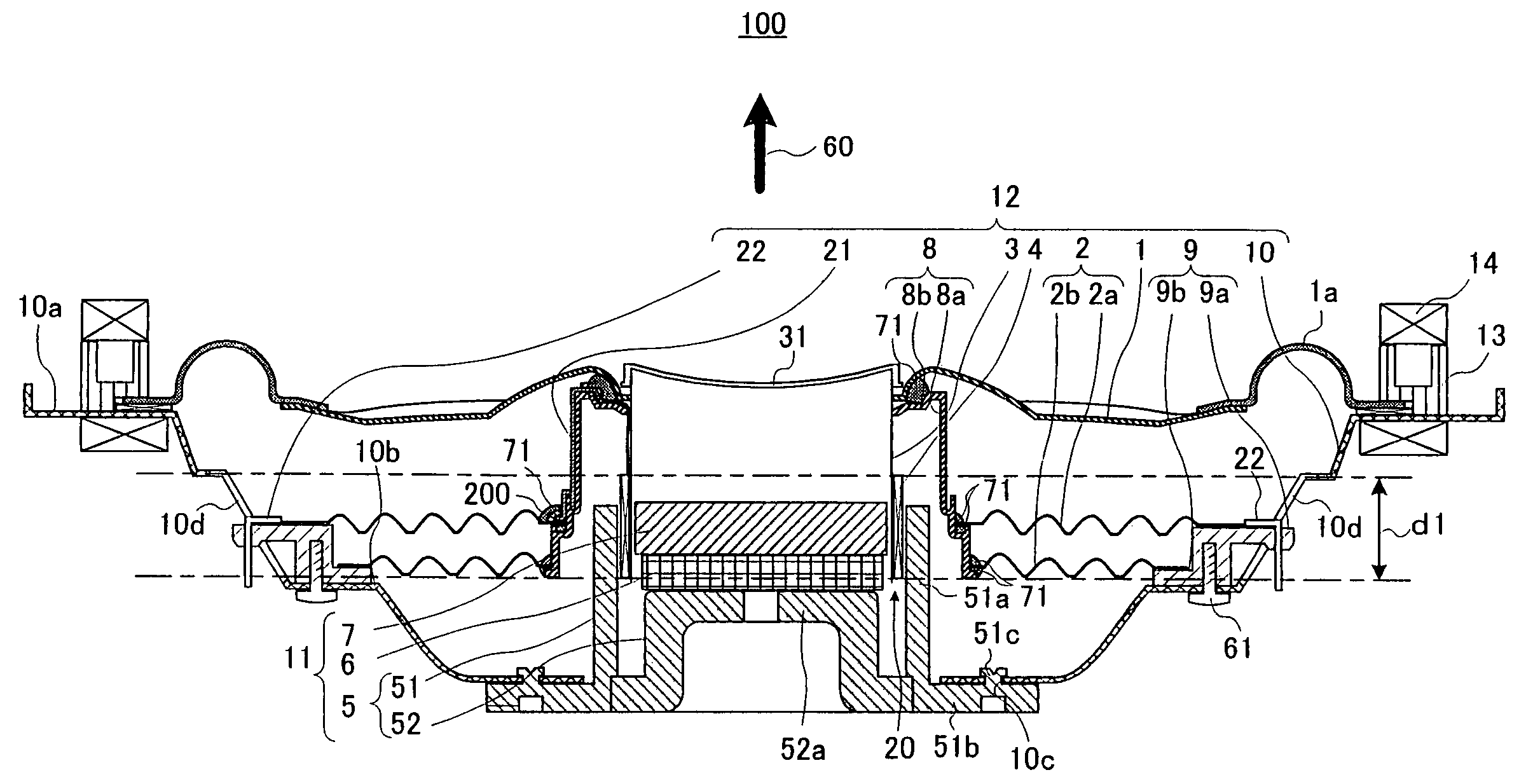
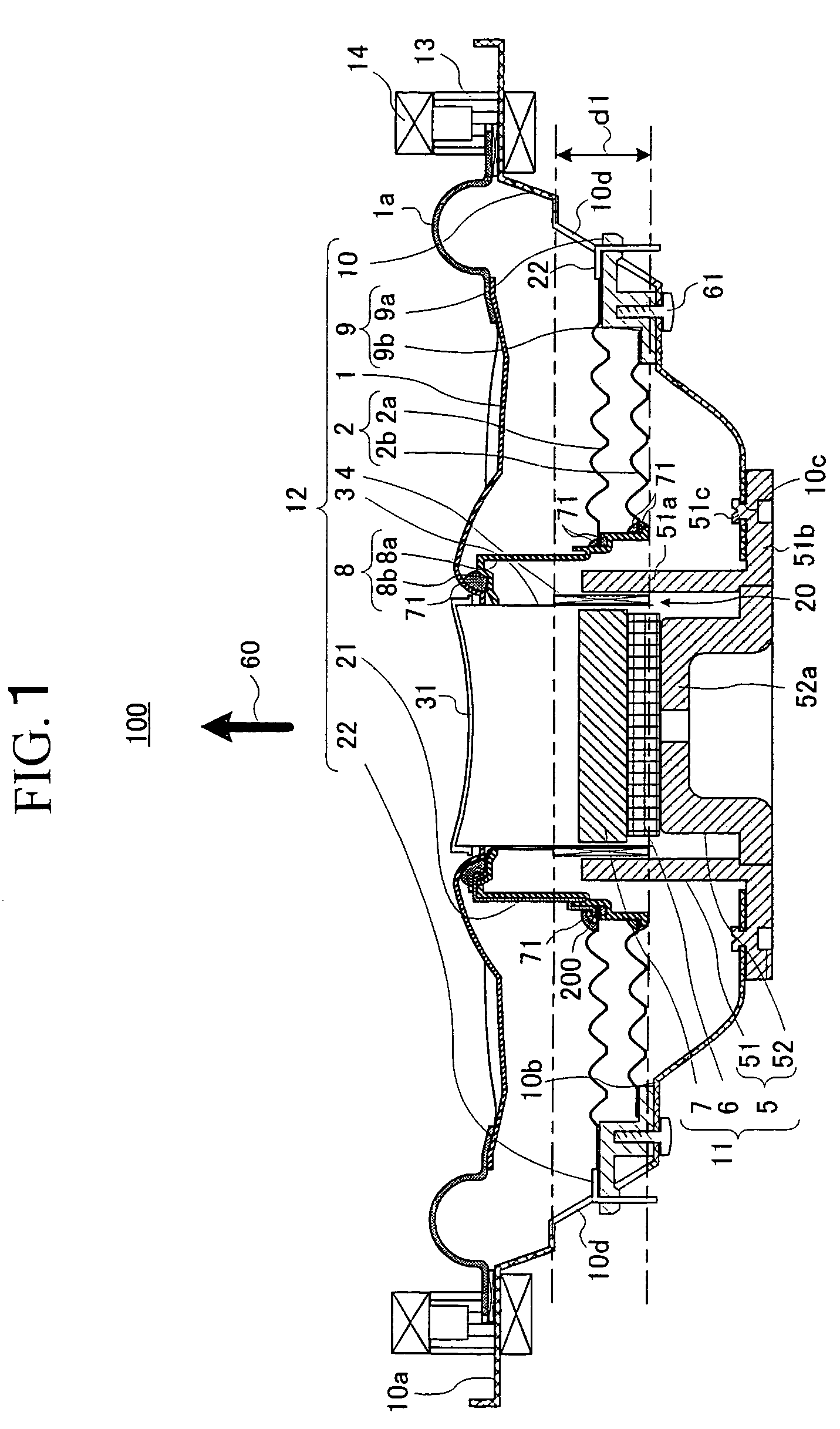
[0018]A preferred embodiment of the present invention will be explained hereinafter with reference to the drawings. This embodiment relates to the structure of supporting the damper in the speaker device. More concretely, a portion, i.e., the inner peripheral edge portion of the damper, is disposed within the winding width of the voice coil, and the inner peripheral edge portion of the damper is fixed to the connecting member fixed to the voice coil bobbin. Thereby, the rolling of the vibrating system including the voice coil bobbin is decreased, and the contact between the vibrating system and the magnetic circuit system including the yoke and the plate is prevented. The occurrence of the abnormal sound is prevented, too.

[0019]A general construction of a speaker device 100 according to the embodiment of the present invention will be schematically shown in FIG. 1. The speaker device 100 of this embodiment can be preferably used as an on-vehicle speaker. FIG. 1 shows a sectional view...


PUM


Abstract

In a speaker device, each inner peripheral edge portion of a conductive damper and an ordinary damper is fixed to an area in the vicinity of a lower end of a cylindrical portion of a connecting member, and each outer peripheral edge portion of them is fixed to a support member. The conductive and ordinary dampers are attached to an area within a constant winding width of a voice coil. When the speaker device is driven, the voice coil bobbin vibrates in an axial direction of the speaker device. The voice coil bobbin sometimes rolls due to various factors. Since a fulcrum of the rolling is within the winding width, a distance r2 from the fulcrum P11 to an intersection of a central axis of the speaker device and a plane surface including a center in the winding width becomes short, and the bobbin hardly rolls.

Description

TECHNICAL FIELD[0001]The present invention relates to a structure of supporting a damper in a speaker device.BACKGROUND ART[0002]Conventionally, there is known an internal-magnet type speaker device including a magnetic circuit having a pot type yoke and a planar plate and a vibrating system including one or more damper, a voice coil bobbin and a voice coil.[0003]Generally, in such the speaker device, the voice coil is wound around an area in the vicinity of a lower end of the voice coil bobbin. The area in the vicinity of the lower end of an inner peripheral wall of the voice coil bobbin is opposed to an outer peripheral wall of the plate fixed on the pot type yoke with a fixed space from each other. At the same time, the area in the vicinity of the lower end of the outer peripheral wall of the voice coil bobbin is opposed to an area in the vicinity of an upper end of a cylindrical portion of the pot type yoke with a fixed space from each other. One or more damper, which is arrange...

Claims


Application Information

Patent Timeline
Patent Type & Authority Patents(United States)
IPC IPC(8): H04R25/00H04R9/04H04R1/00H04R7/12H04R9/02H04R9/06H04R11/02
CPCH04R9/06H04R7/12
Inventor WATANABE, TOMOYUKI
Owner PIONEER CORP
Why Eureka
Try Eureka