

Power Transmission Chain and Power Transmission Device Using the Same
- Summary
- Abstract
- Description
- Claims
- Application Information
AI Technical Summary
Benefits of technology
Problems solved by technology
Method used
Image

Examples
first embodiment
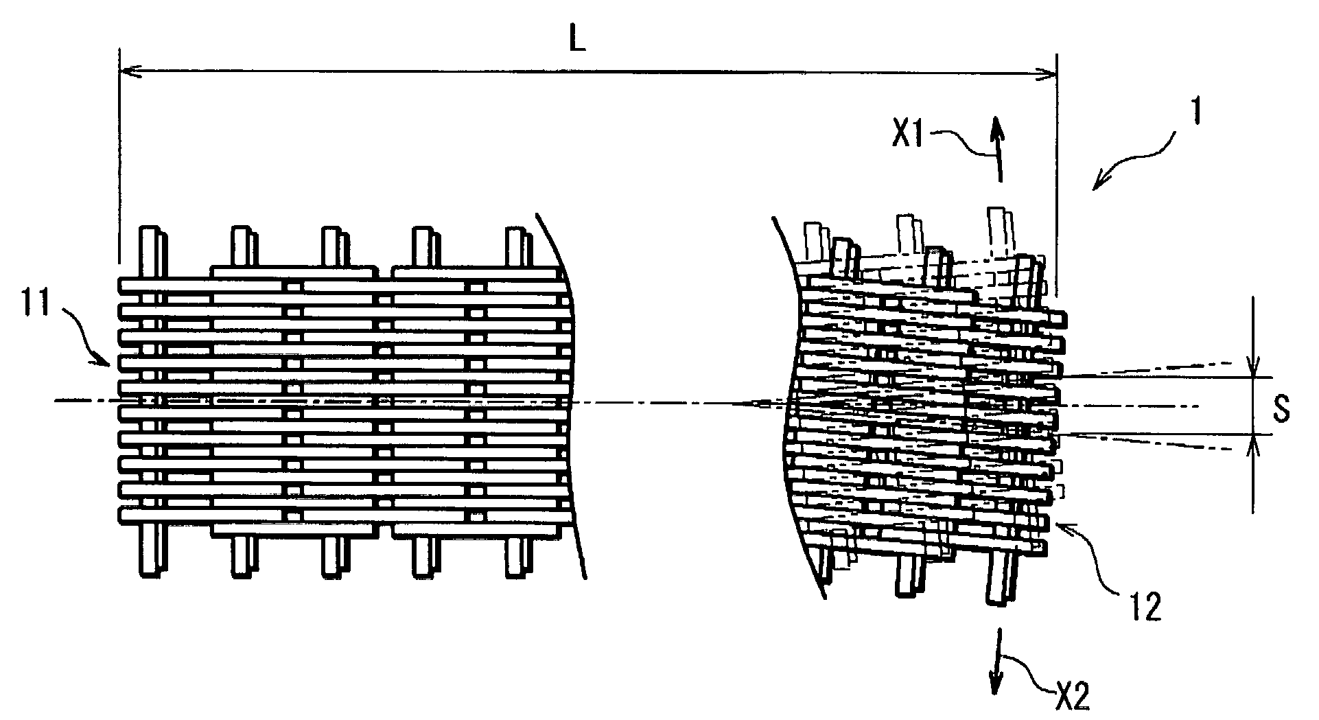
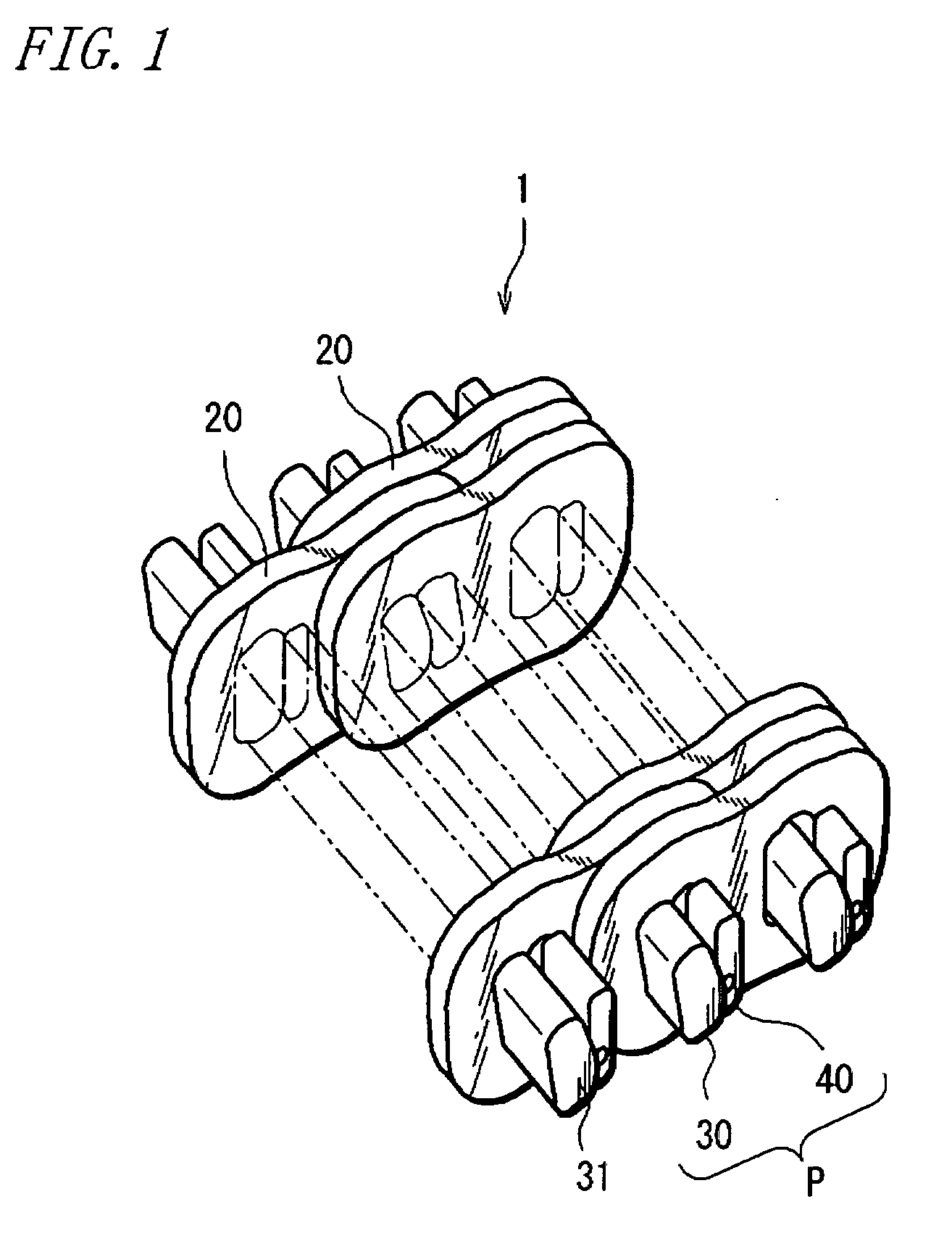
[0046]Next, preferred embodiments of the present invention will be described with reference to the accompanying drawings. FIG. 1 is a schematic perspective view of a configuration of essential portions of a chain for a chain-type continuously variable transmission (hereinafter also simply referred to as “chain”) according to a power transmission chain of the present invention. In the figure, the chain 1 of the embodiment is endless, and includes, as chain components, a plurality of link plates 20 made of metal (such as carbon steel), and a plurality of pin members P made of metal (such as bearing steel) for connecting the link plates 20 to one another. In FIG. 1, a center portion in a width direction of the chain 1 is partly omitted.
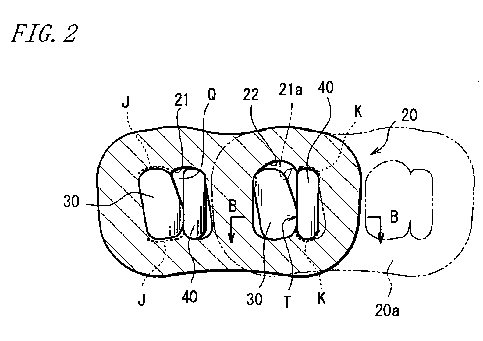
[0047]FIG. 2 is a circumferential sectional view of part of the chain 1. The link plates 20 each have a contour line of gentle curved shape, and are formed to have substantially the same contours. Each link plate 20 has a first through hole 21 and a seco...
fourth embodiment
[0114]In the chain 1 according to the embodiment is, as in the fourth embodiment, centrally concentrated pitch portions 65 are surely connected at equal intervals in the chain circumferential direction. The centrally concentrated pitch portion 65 is different from the centrally dense pitch portion in that no link plate 20 is arranged near opposite ends of the entire chain width G. The entire chain width G is a width of a pitch portion arranged with the widest width in the chain width direction in the chain 1 in FIG. 21. The centrally concentrated pitch portion 65 includes two sets of pin members P2 and nine link plates 204, and all the nine link plates 204 arranged between the two sets of pin members P2 are arranged on one another substantially without gaps around the center in the width direction of the chain 1.
[0115]Then, pitch portions 66 connected adjacent to opposite ends in the chain circumferential direction of the centrally concentrated pitch portion 65 includes ten link pla...
PUM
 Abstract
Description
Claims
Application Information