

Electric wire holding structure for electric compressor and electric wire holding method for electric compressor
- Summary
- Abstract
- Description
- Claims
- Application Information
AI Technical Summary
Benefits of technology
Problems solved by technology
Method used
Image

Examples
Embodiment Construction
[0059]Hereinafter, an electric wire holding structure for an electric compressor and an electric wire holding method for an electric compressor according to the present invention will be explained referring to figures.
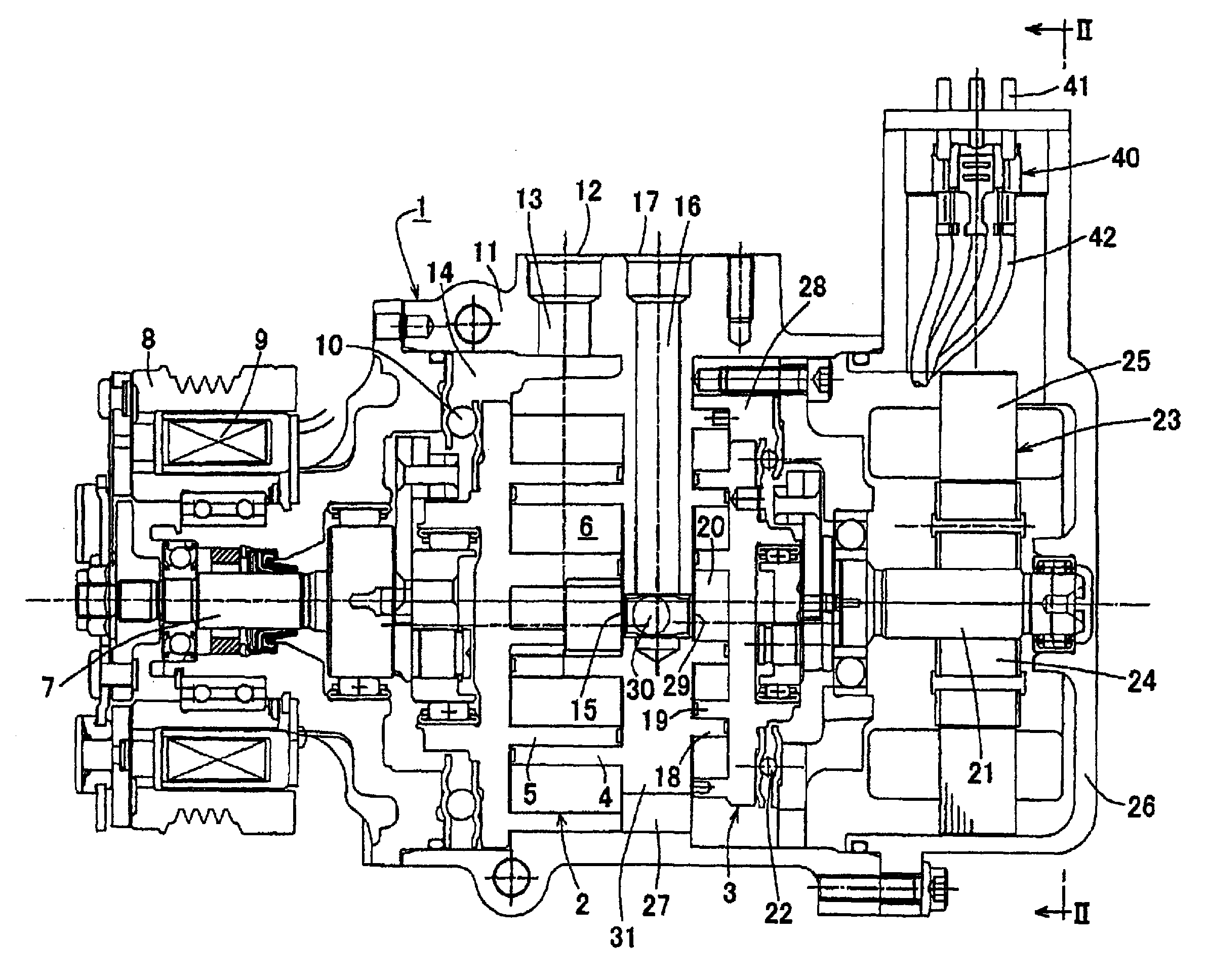
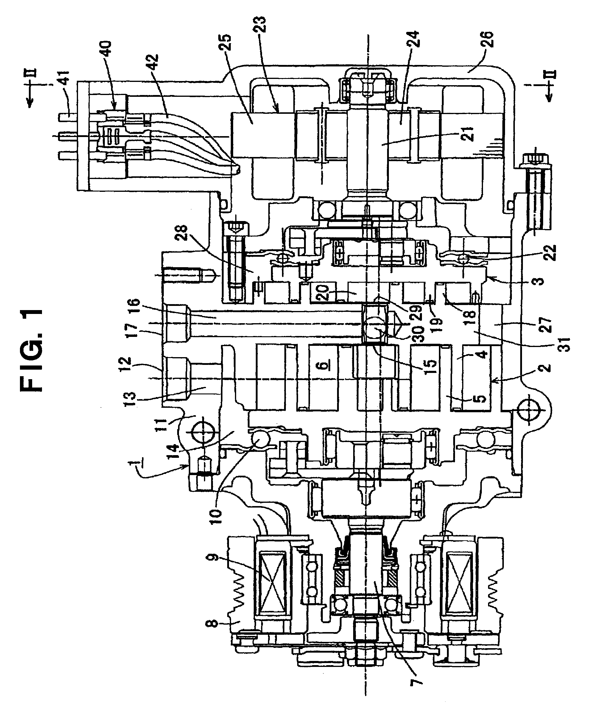
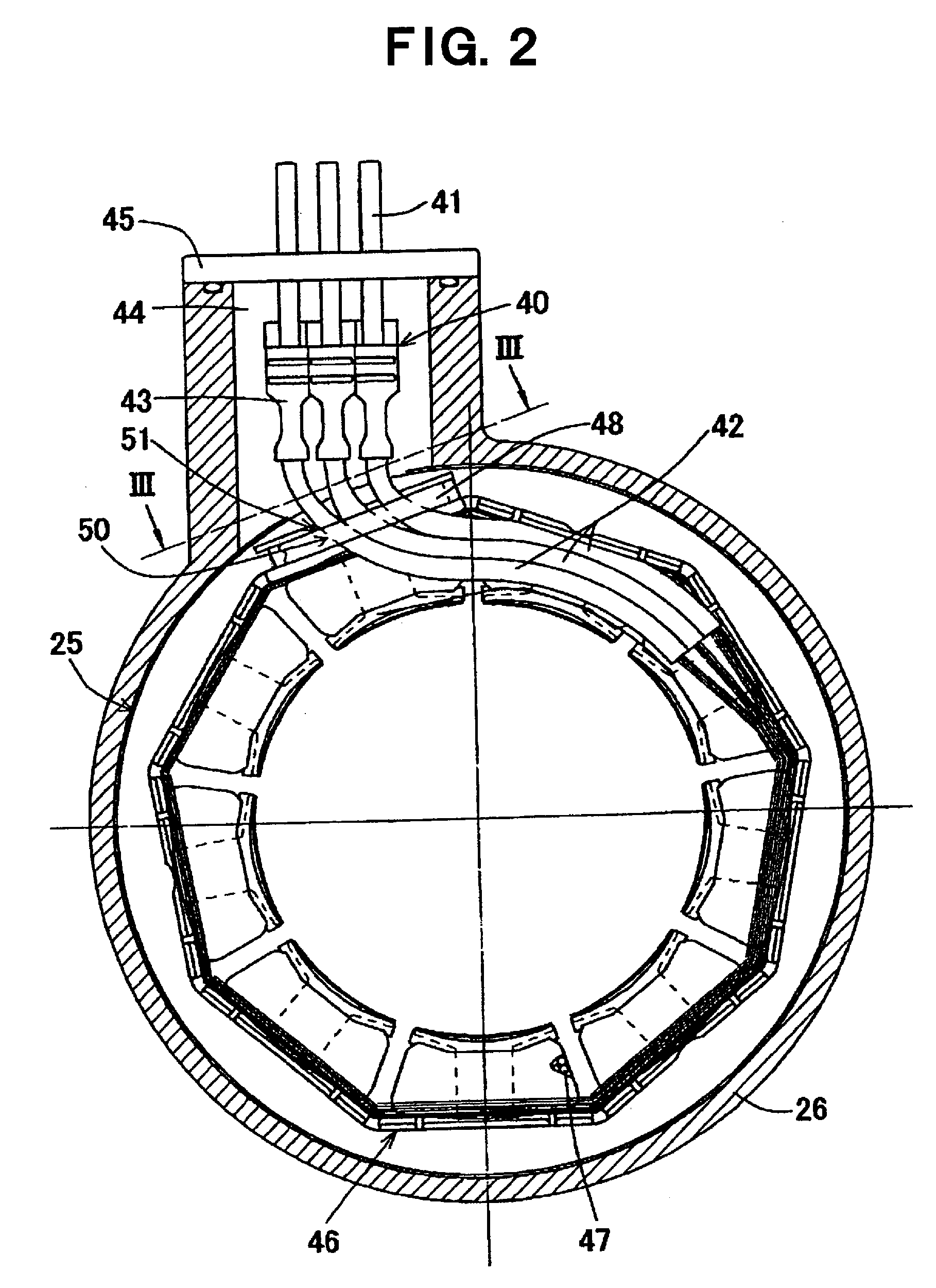
[0060]FIGS. 1 to 3 depict an electric compressor in which an input electric wire of an incorporated motor is held using an electric wire holding structure for an electric compressor according to a first embodiment of the present invention. In FIG. 1, the electric compressor is constructed as a hybrid compressor 1.
[0061]First, the hybrid compressor depicted in FIG. 1 will be explained. Hybrid compressor 1 is formed as a scroll type compressor, and has a first compression mechanism 2 and a second compression mechanism 3. First compression mechanism 2 has a fixed scroll 4, a movable scroll 5 forming a plurality of pairs of operational spaces (fluid pockets) 6 by engaging with fixed scroll 4, a drive shaft 7 driving movable scroll 5 at an orbital movement by engaging with ...
PUM
 Abstract
Description
Claims
Application Information