
Low-gain low-sidelobe micro-base station antenna

A low-gain, antenna technology, applied to antennas, antenna arrays, antenna grounding devices, etc., can solve problems such as the decrease of the receiving sensitivity of the inaccessible antenna to the interference signal, the reduction of the radiated power of the array, and the decrease of the receiving sensitivity. Appropriate and clear effect

Pending Publication Date: 2017-11-07
TONGYU COMM INC
View PDF7 Cites 6 Cited by
  • Summary
  • Abstract
  • Description
  • Claims
  • Application Information

AI Technical Summary

Problems solved by technology

Although the output power of the transmitter can be reduced, thereby reducing the radiated power of the array, it cannot reduce the antenna's sensitivity to interference signals
Of course, the decrease in receiving sensitivity will also make the receiving signal-to-noise ratio of useful signals worse

Method used


Image

  • Low-gain low-sidelobe micro-base station antenna
  • Low-gain low-sidelobe micro-base station antenna
  • Low-gain low-sidelobe micro-base station antenna

Examples


Embodiment Construction

[0046] The preferred embodiments of the present invention are given below in conjunction with the accompanying drawings to describe the technical solution of the present invention in detail. It should be noted that the preferred embodiments described here are only used to illustrate and explain the present invention, and are not used to limit or limit the present invention.

[0047] The present invention aims to design a densely deployed broadband, directional, wide beam, low side lobe, low gain, low efficiency, miniaturization, low profile, and low-cost small base station or micro base station for the 5.8G frequency band of cellular mobile communication. Base station antennas, and provide effective or beneficial reference methods for the optimal design of low-gain, low-sidelobe directional antennas in other frequency bands.

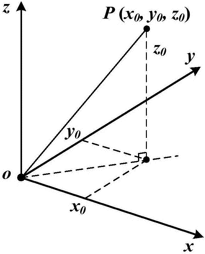
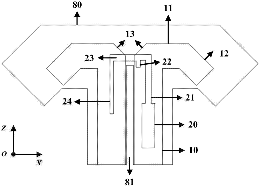
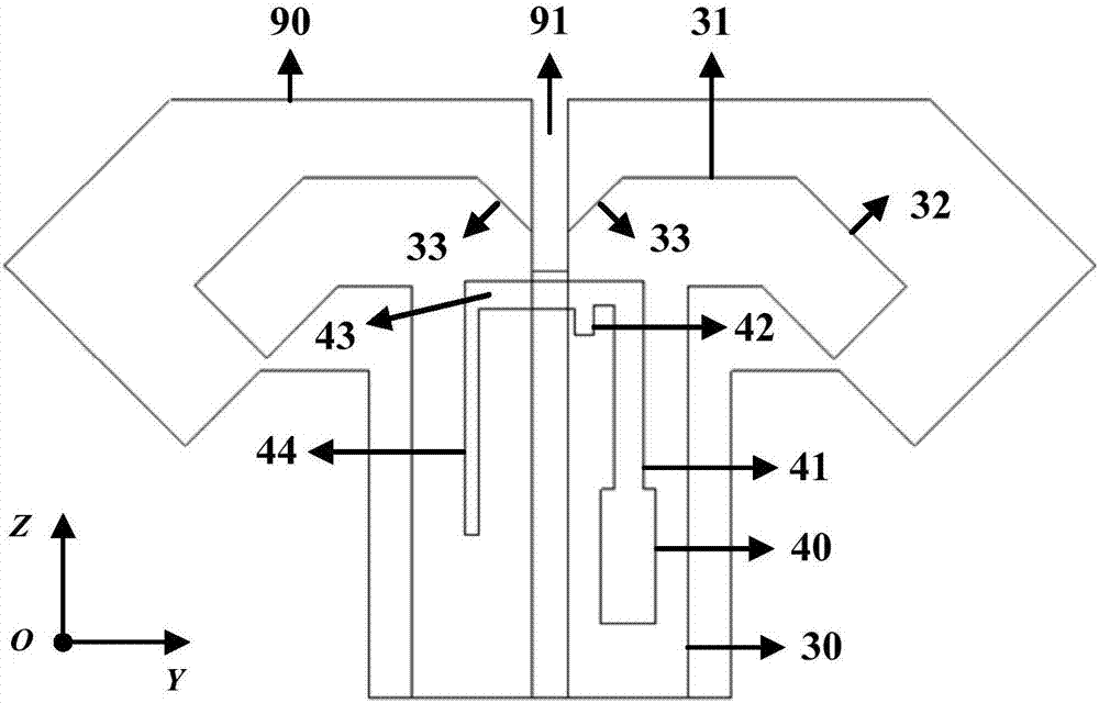
[0048] see Figure 1-12 , the present invention constructs the low-gain and low-sidelobe micro base station antenna by the following method:

[0049] ...


PUM


Abstract

A low-gain low-sidelobe micro-base station antenna of the present invention comprises N pairs of crossed vibrators arranged in array and disposed on the floor, each pair of crossed vibrators include two cross-placed pendulous broadband vibrators, and the two pendulous broadband vibrators are respectively printed on two dielectric substrates; a microstrip line is arranged on the other side of the dielectric substrate opposite to the pendulous broadband vibrator; two printed feed networks are arranged on the floor to respectively feed the two subarrays of the array; and the input ends of the feed networks are provided with two-stage cascaded Wilkinson power splitters. The Wilkinson power splitters feed each array element through each power splitting branch, wherein N is a natural number larger than and equal to 2. The invention designs the densely disposed small base station or micro base station antenna of broadband, direction, wide beam, low sidelobe, low gain, low efficiency, miniaturization, low profile and low cost for cellular mobile communication 5.8G band, and provides an effective or beneficial reference method for optimizing the design of low gain and low sidelobe directional antennas in other frequency bands.

Description

【Technical field】 [0001] The present invention relates to cellular mobile communication base station antenna equipment and technology, in particular to a low gain and low side lobe micro base station antenna. 【Background technique】 [0002] With the continuous increase of network deployment density, mobile communication has basically achieved wide-area continuous coverage of signals. However, limited by the operating frequency band and wide coverage area, it is difficult for macro cells to meet the requirements of high data transmission rate and large system capacity. In contrast, the 5.8G frequency band has wide bandwidth, large capacity, good propagation characteristics, and small antenna size, which is very suitable for local high-speed data services with dense users. This type of small and micro base station antenna needs to have the characteristics of large bandwidth (5.15~5.85GHz, BW=12.73%), wide (horizontal) wave width, and MIMO, so as to cover a large area and serv...

Claims


Application Information

Patent Timeline
Patent Type & Authority Applications(China)
IPC IPC(8): H01Q1/50H01Q1/38H01Q1/48H01Q21/00H01Q21/08
CPCH01Q1/38H01Q1/48H01Q1/50H01Q21/0006H01Q21/08
Inventor 李道铁吴中林刘木林
Owner TONGYU COMM INC
Learn More