
Method and apparatus for automatic visual detection, recording, and retrieval of events

a technology of automatic visual detection and event detection, applied in the field of high-speed video event detection, motion analysis, image recording, and automated image analysis, can solve the problems of special challenges, insufficient detection of the intensity of light transmitted or reflected by one or more points, and difficulty in adjustment, etc., to achieve specific effects

Active Publication Date: 2005-12-15
COGNEX TECH & INVESTMENT
View PDF99 Cites 26 Cited by
  • Summary
  • Abstract
  • Description
  • Claims
  • Application Information

AI Technical Summary

Benefits of technology

The invention provides methods and systems for automatically detecting and recording events using a visual detector. The events can be any specific condition that occurs within the field of view of the detector, such as a mechanical process or a moving object. The detector captures a sequence of frames and analyzes them using various methods to determine if an event is occurring and when it occurs. The recorded frames can be displayed for a human user or further analyzed by an image analysis system. The technical effects of the invention include improved automation of event detection, improved accuracy of event detection, and improved efficiency of recording and retrieving event frames.

Problems solved by technology

The fact that these events are both rare and short-duration creates special challenges.
Using photodetectors to provide a trigger signal has some limitations, however, including a simple measure of the intensity of light transmitted or reflected by one or more points may be insufficient for detecting the event; it can be difficult to adjust the position of each photodetector so that it is looking at the exact right point; the points to be measured must not move around during normal operation of the mechanical process; and the need for multiple photodetectors can make installation and setup difficult.
A machine vision system has its own limitations, however, including: machine vision systems are generally only suitable when the event relates to the inspection of discrete objects; and machine vision systems are generally too slow to detect short-duration events, and must instead look for some long-duration condition caused by that event, such as a defective product.
It does not see and cannot analyze the images captured by that device, the very images that contain the event that is to be detected.
Even if those images could be made available to a machine vision system, they are produced at far too high a rate to be analyzed by machine vision systems of conventional design.
These frames may not be strictly consecutive, however, because as the object passes through the field of view there may be some viewing perspectives, or other conditions, for which the evidence that the object is located in the field of view is not sufficient.

Method used


Image

  • Method and apparatus for automatic visual detection, recording, and retrieval of events
  • Method and apparatus for automatic visual detection, recording, and retrieval of events
  • Method and apparatus for automatic visual detection, recording, and retrieval of events

Examples


Embodiment Construction

Basic Operation of the Invention

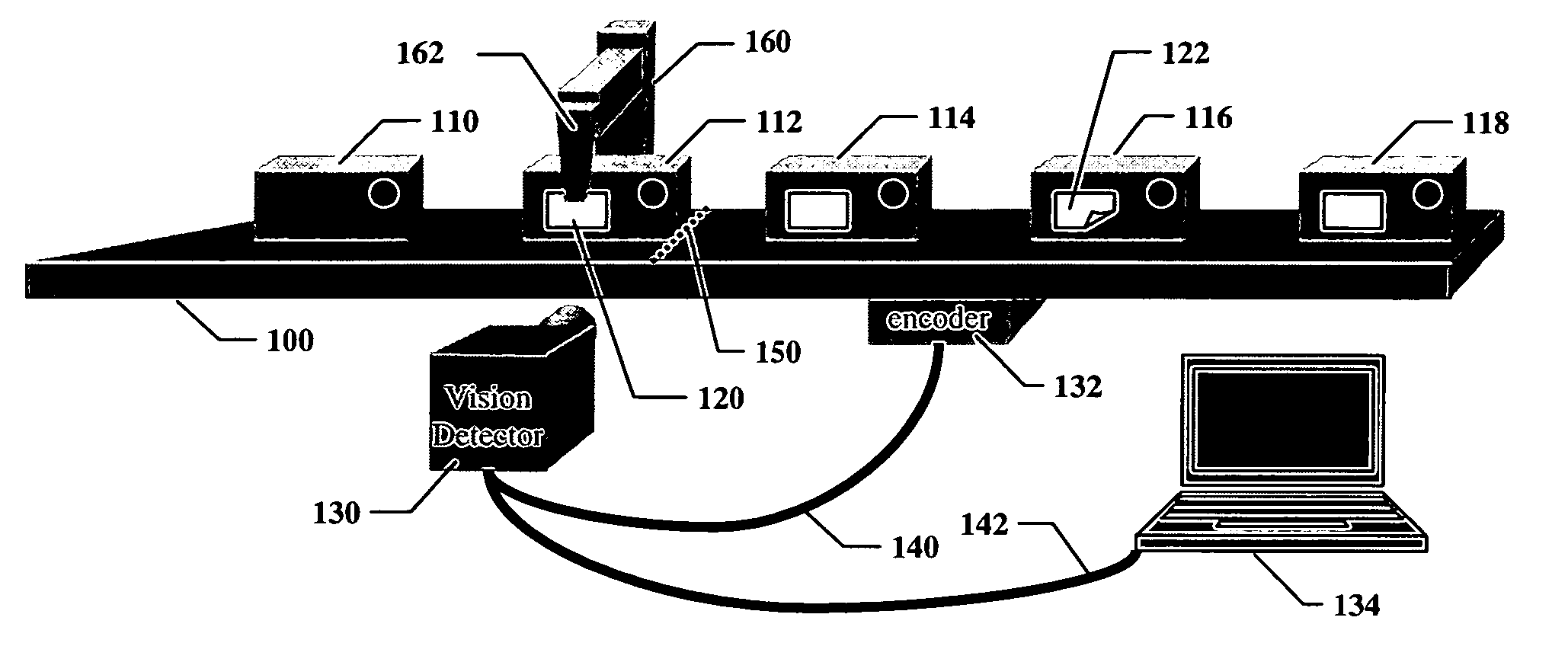
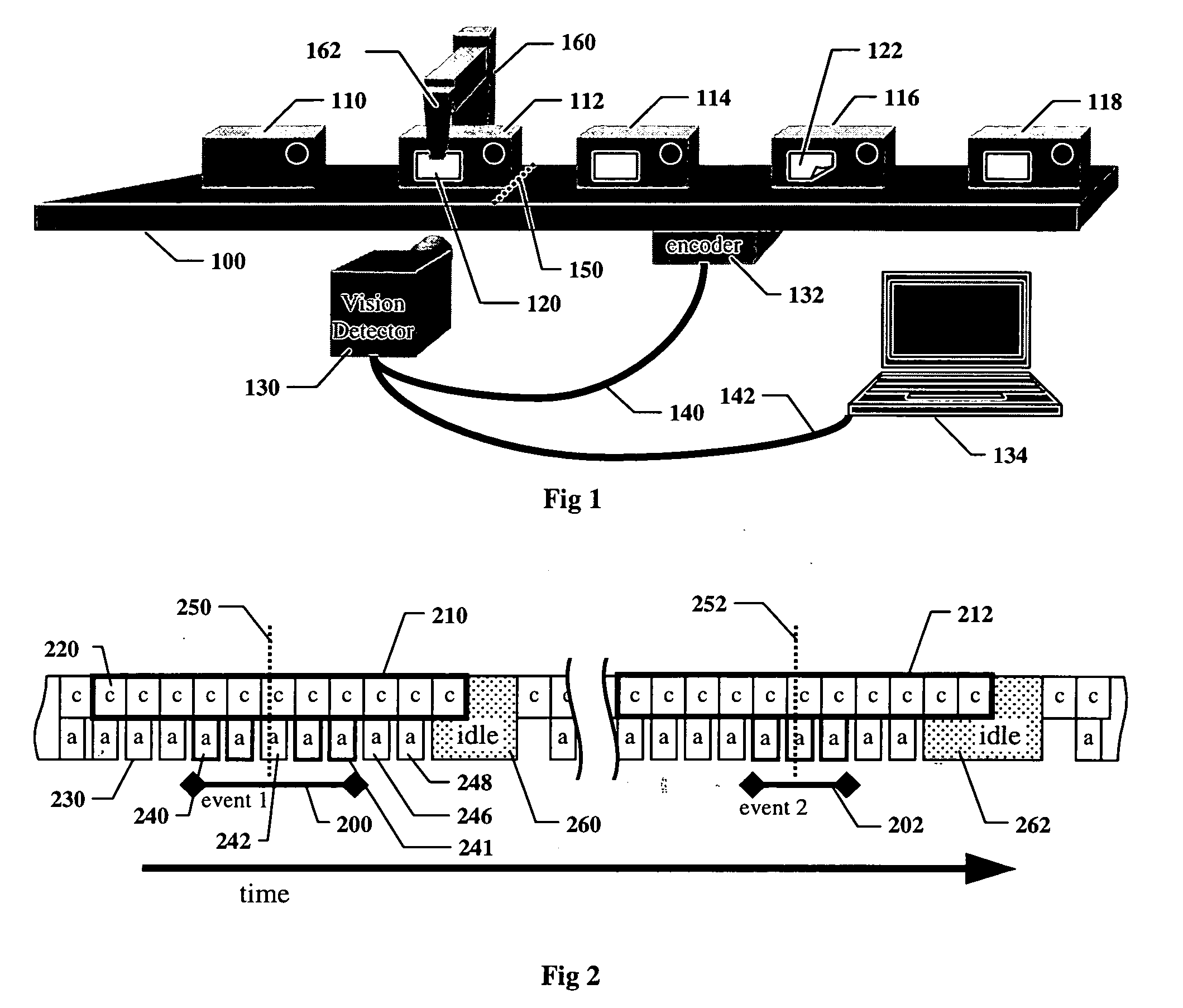
[0100]FIG. 1 shows an illustrative embodiment of a vision detector configured to detect certain events that may occur on a production line, and to record and retrieve images of those events. A conveyer 100 transports objects, including example objects 110, 112, 114, 116, and 118, left to right past a labeling mechanism 160, which acts to place a label on each object, for example label 120 on object 112. The labeling mechanism 160 includes an arm 162 that acts so as to move and apply each label to each object. Note that labeling mechanism 160 and arm 162 are shown for illustrative purposes to explain the invention, and do not necessarily represent any particular mechanism used to apply labels in industrial production.

[0101] The labeling mechanism 160 may occasionally malfunction, resulting for example in the misapplied label 122, whose lower right corner is bent away from the surface of object 116. Many industrial productions lines will use some for...


PUM


Abstract

Disclosed are methods and apparatus for automatic visual detection of events, for recording images of those events and retrieving them for display and human or automated analysis, and for sending synchronized signals to external equipment when events are detected. An event corresponds to a specific condition, among some time-varying conditions within the field of view of an imaging device, that can be detected by visual means based on capturing and analyzing digital images of a two-dimensional field of view in which the event may occur. Events may correspond to rare, short duration mechanical failures for which obtaining images for analysis is desirable. Events are detected by considering evidence obtained from an analysis of multiple images of the field of view, during which time moving mechanical components can be seen from multiple viewing perspectives.

Description

RELATED APPLICATION [0001] This application is a continuation-in-part of co-pending U.S. patent application Ser. No. 10 / 865,155, entitled METHOD AND APPARATUS FOR VISUAL DETECTION AND INSPECTION OF OBJECTS, by William M. Silver, filed Jun. 9, 2004, the teachings of which are expressly incorporated herein by reference, and referred to herein as the “Vision Detector Method and Apparatus”.BACKGROUND OF THE INVENTION [0002] 1. Field of the Invention [0003] The invention relates to high-speed video event detection, motion analysis, image recording, and automated image analysis. [0004] 2. Description of the Related Art [0005] It is well-known in the art to use high-speed image recording devices for motion analysis of mechanical systems that operate too fast for the human eye to see. These devices capture and record hundreds or thousands of images per second of some mechanical process, and then display those images, in slow motion or as still pictures, for human users to see and analyze th...

Claims


Application Information

Patent Timeline
Patent Type & Authority Applications(United States)
IPC IPC(8): G06K9/00G06T7/20
CPCG06T7/20
Inventor SILVER, WILLIAM M.PHILLIPS, BRIAN S.
Owner COGNEX TECH & INVESTMENT
Learn More