

Golf club head with adjustable vibration-absorbing capacity
- Summary
- Abstract
- Description
- Claims
- Application Information
AI Technical Summary
Benefits of technology
Problems solved by technology
Method used
Image

Examples
first embodiment
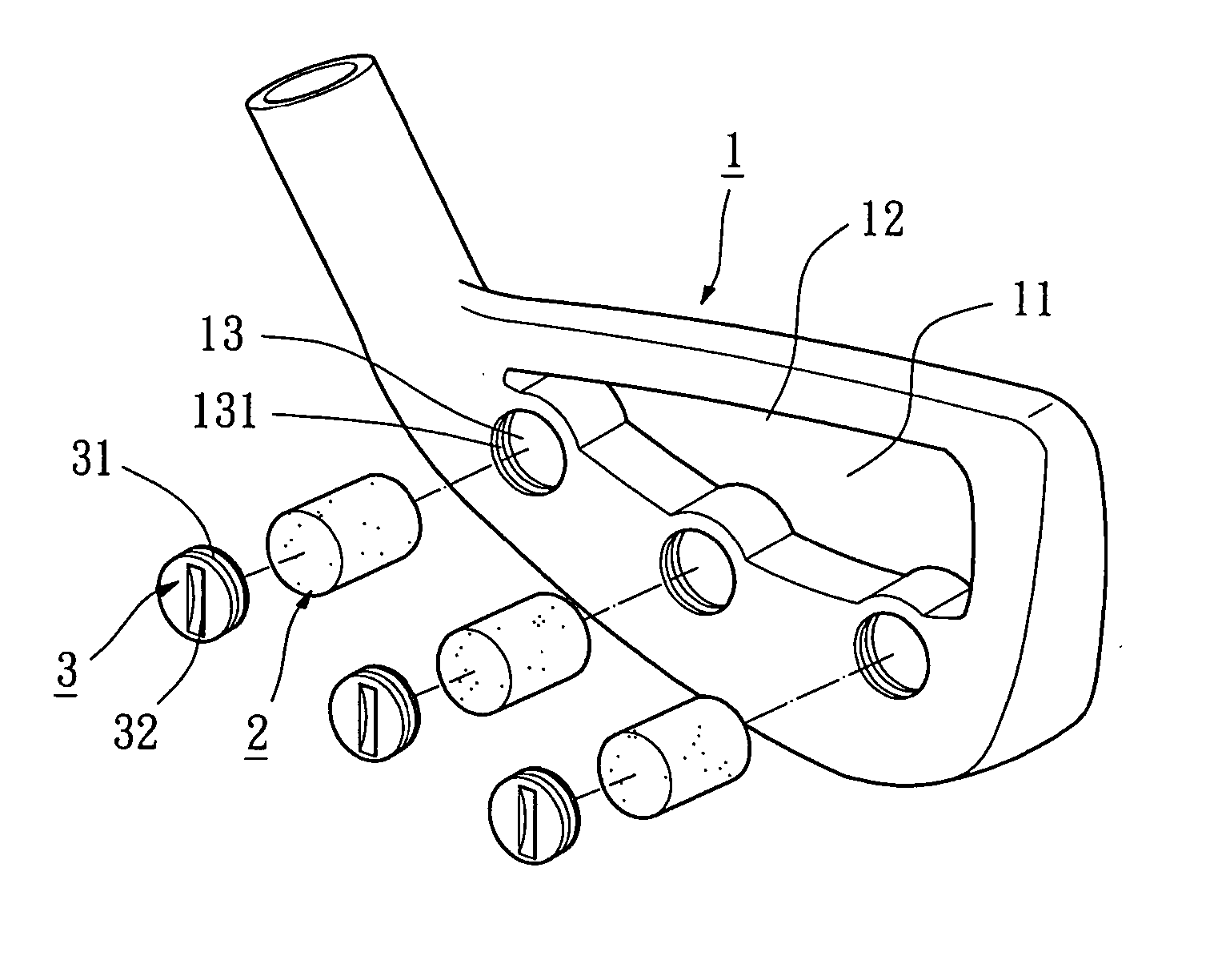
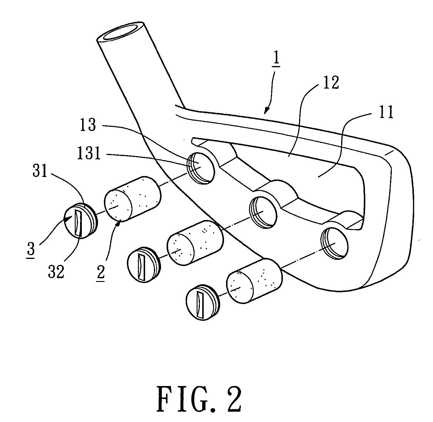
[0027] Referring to FIGS. 2 and 3, a golf club head in accordance with the present invention comprises a body 1, at least one vibration-absorbing member 2 (three in this embodiment), and at least one adjusting member 3 (three in this embodiment). The body 1 is a body for an iron club head. The body 1 is engaged with a striking plate 11 and includes a back cavity 12 and at least one compartment 13 (three in this embodiment). The body 1 can be engaged with the striking plate 11 by welding, brazing, insertion, or screwing. The striking plate 11 has a front side for striking golf balls. Alternatively, the body 1 and the striking plate 11 can be integrally formed with each other, with the striking plate 11 being a striking face of the body 1 for striking golf balls.
[0028] The back cavity 12 is defined in a rear side of the body 1. The rear side of the striking plate 11 is thus exposed. Each compartment 13 is defined in a lower portion of the rear side of the body 1 and includes a rearwar...
second embodiment
[0037]FIG. 4 illustrates the invention, wherein the gas chamber 22 may contain an appropriate amount of liquid 23 and an appropriate amount of gas. The liquid 23 may be water, oil, gel-like fluid, non-corrosive water solution, organic solution, mixed solution, or viscous solution. When hitting a golf ball with the body 1, the liquid 23 in the gas chamber 22 provides a damping effect due to viscosity, thereby absorbing the residual vibrations of the body 1. Further, the gas in the gas chamber 22 maintains the compression characteristics of gas for the vibration-absorbing member 2. It is noted that the back cavity 12 is communicated with the compartments 13, allowing greater deformation of the vibration-absorbing members 2.
third embodiment
[0038]FIG. 5 illustrates the invention, wherein each vibration-absorbing member 2 is solid and slidably received in the associated compartment 13. As mentioned above, each adjusting member 3 can be turned to adjust the pressing force exerting on the rear side of the striking plate 11 by the vibration-absorbing member 2 and to adjust the compressed amount of the vibration-absorbing member 2. Thus, before hitting a golf ball, if an adjusting member 3 is turned to press against the associated vibration-absorbing member 2 to a greater extent, the associated vibration-absorbing member 2 is pre-loaded with a pre-loaded stress and pre-pressed to a smaller volume. Thus, the associated vibration-absorbing member 2 presses against the striking plate 11 to a greater extent and thus has a higher vibration-absorbing capacity. On the other hand, if the adjusting member 3 is turned to press against the associated vibration-absorbing member 2 to a smaller extent or to be in loose contact with the a...
PUM
 Abstract
Description
Claims
Application Information