

Crowd control system for a loader
a control system and loader technology, applied in agricultural machines, applications, instruments, etc., can solve the problems of increasing the actuator force, the linkage of the loader, and increasing the cycle time, so as to reduce the crowd force and reduce the motive power
- Summary
- Abstract
- Description
- Claims
- Application Information
AI Technical Summary
Benefits of technology
Problems solved by technology
Method used
Image

Examples
Embodiment Construction
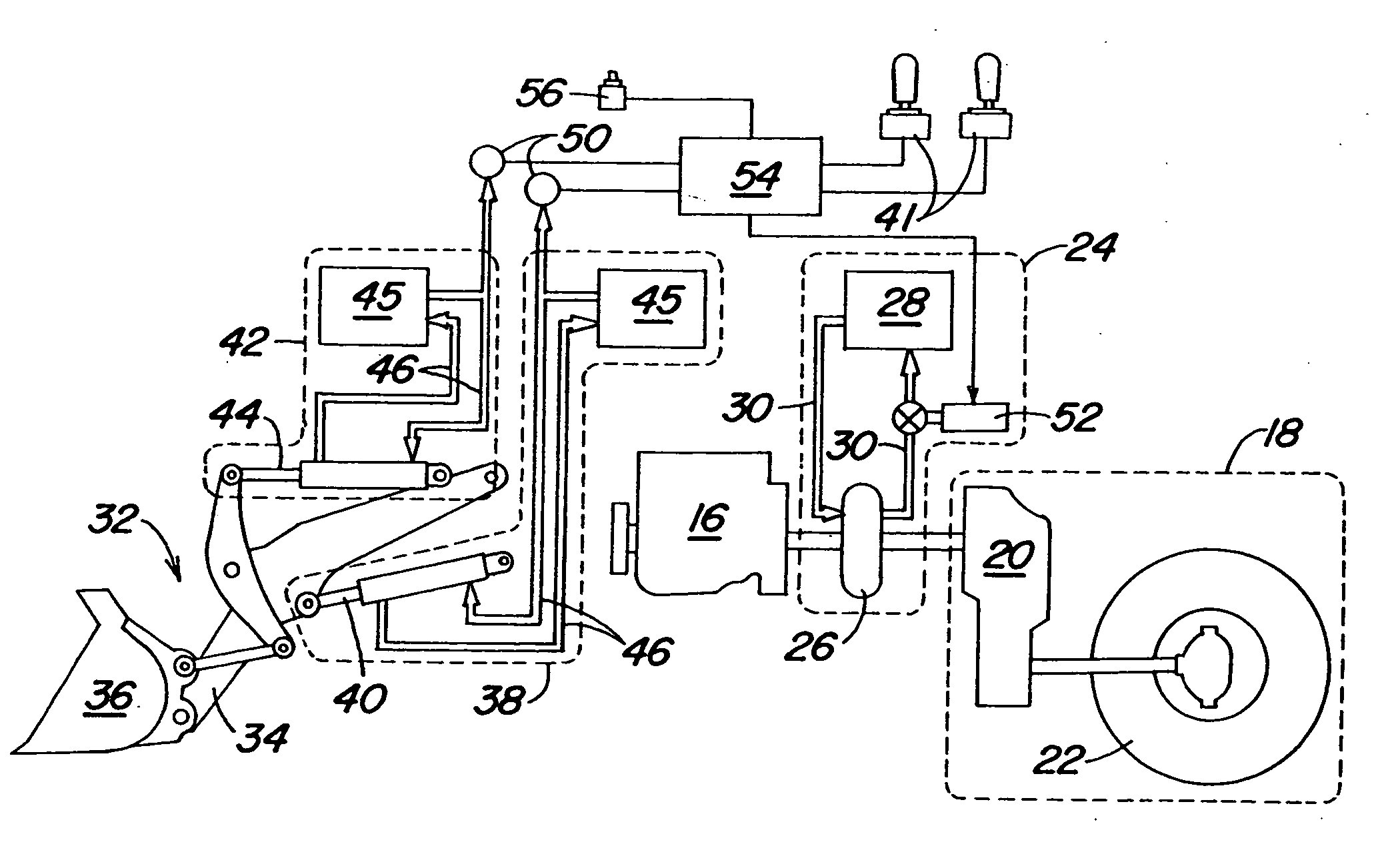
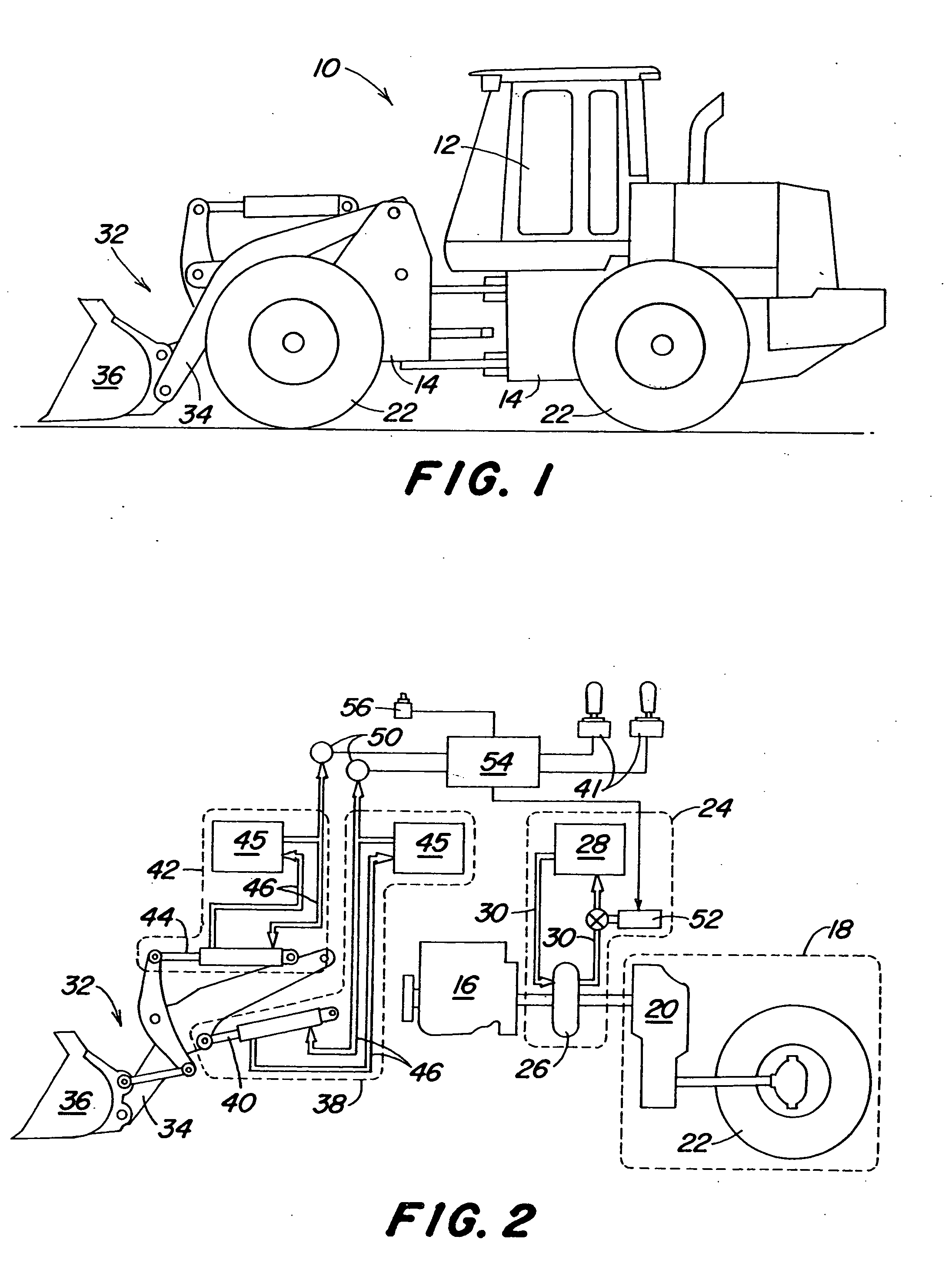
[0010]FIG. 1 illustrates a self-propelled work vehicle, such as a loader 10. An operator controls the functions of the vehicle from an operator's station 12. The loader 10 has a frame 14, and an engine 16 that powers the vehicle. The engine 16 powers a drive unit 18 comprising a transmission 20 connected to ground engaging wheels 22 that support and propel the vehicle. Although the present invention is illustrated as being used on a loader 10 with ground engaging wheels 22 as ground engaging portions, it could also be used on loaders having ground engaging belts or tracks as the ground engaging portions.
[0011] In the embodiment illustrated in FIG. 2, a fluid coupling 24 couples the engine 16 and the transmission 20 to one another. More specifically, the fluid coupling 24 in the illustrated embodiment includes a torque converter 26. The torque converter 26 is supplied with lubrication fluid 30 by a lubrication circuit 28. The lubrication fluid 30 is utilized by the torque converter ...
PUM
 Abstract
Description
Claims
Application Information